LT6700/LT6700HV
9
6700123fh
For more information www.linear.com/LT6700
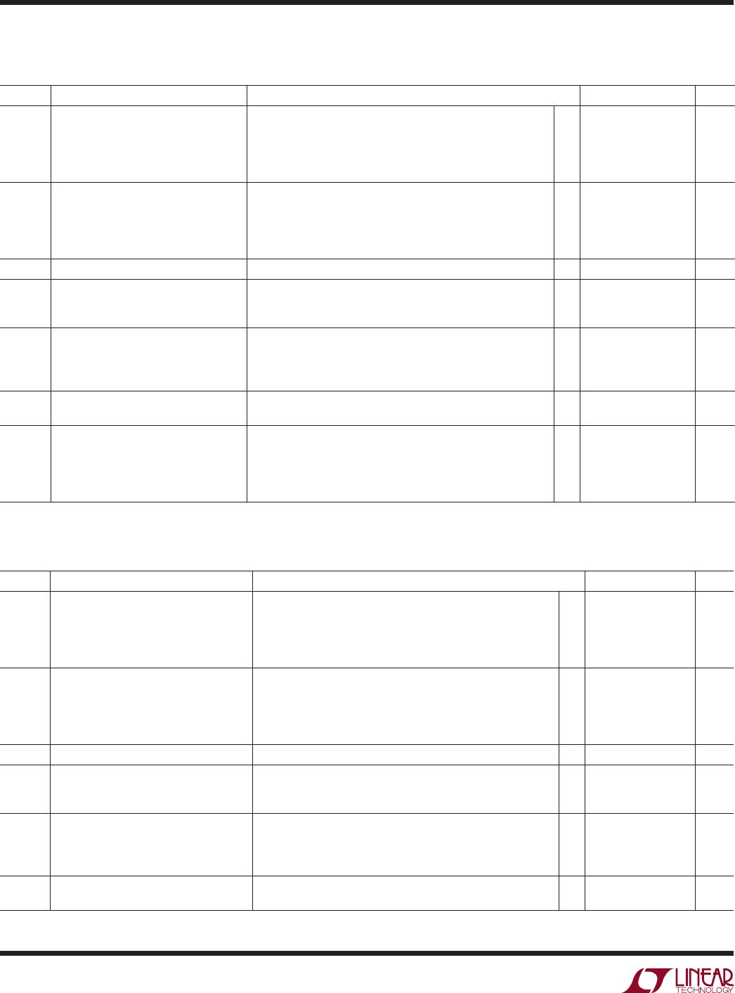
ELECTRICAL CHARACTERISTICS
SYMBOL
PARAMETER
CONDITIONS
MIN
LT6700H
TYP
MAX
UNITS
V
TH(R)
Rising Input Threshold Voltage
(Note 6)
R
L
= 100k, V
O
= 2V Swing
V
S
= 1.4V
V
S
= 5V
V
S
= 12V
V
S
= 18V
l
l
l
l
390
392
389
388
411
410
412
413
mV
mV
mV
mV
V
TH(F)
Falling Input Threshold Voltage
(Note 6)
R
L
= 100k, V
O
= 2V Swing
V
S
= 1.4V
V
S
= 5V
V
S
= 12V
V
S
= 18V
l
l
l
l
381.5
382.5
380.5
379.5
405.5
404.5
406.5
407.5
mV
mV
mV
mV
HYS HYS = V
TH(R)
– V
TH(F)
V
S
= 1.4V, 5V, 12V, 18V, R
L
= 100k, V
O
= 2V Swing
l
2 13.5 mV
I
B
Input Bias Current V
S
= 1.4V, 18V, V
IN
= V
S
V
S
= 1.4V, V
IN
= 18V, 36V
V
S
= 1.4V, 18V, V
IN
= 100mV
l
l
l
±45
±45
±50
nA
nA
nA
V
OL
Output Low Voltage 10mV Input Overdrive
V
S
= 1.4V, I
OUT
= 0.1mA
V
S
= 1.6V, I
OUT
= 3mA
V
S
= 5V, I
OUT
= 5mA
l
l
l
250
250
250
mV
mV
mV
I
OFF
Output Leakage Current V
S
= 1.4V, 18V, V
OUT
= V
S
, V
IN
= 40mV Overdrive
V
S
= 18V, V
OUT
= 18V, (36V, R
L
= 100k), V
IN
= 40mV Overdrive
l
l
1
1
µA
µA
I
S
Supply Current No Load Current
V
S
= 1.4V
V
S
= 5V
V
S
= 12V
V
S
= 18V
l
l
l
l
16.0
17.0
18.5
19.0
µA
µA
µA
µA
The l denotes the specifications which apply over the temperature range of –40°C ≤ T
A
≤ 125°C, (LT6700HVH-1/LT6700HVH-2/
LT6700HVH-3) unless otherwise specified (Notes 4, 5).
SYMBOL PARAMETER CONDITIONS MIN TYP MAX UNITS
I
S
Supply Current No Load Current
V
S
= 1.4V
V
S
= 5V
V
S
= 12V
V
S
= 18V
l
l
l
l
14.0
15.0
16.5
17.0
µA
µA
µA
µA
The l denotes the specifications which apply over the temperature range of –40°C ≤ T
A
≤ 85°C, (LT6700HVI-1/LT6700HVI-2/LT6700HVI-3)
unless otherwise specified (Notes 4, 5).
Note 1: Stresses beyond those listed under Absolute Maximum Ratings
may cause permanent damage to the device. Exposure to any Absolute
Maximum Rating condition for extended periods may affect device
reliability and lifetime.
Note 2: A heat sink may be required to keep the junction temperature
below the absolute maximum rating when the output is shorted
indefinitely.
Note 3: The inputs are protected by ESD diodes to the ground. If the input
voltage exceeds –0.3V below ground, the input current should be limited
to less than 10mA.
Note 4: The LT6700C-1/-2/-3/LT6700HVC-1/-2/-3, and
LT6700I-1/-2/-3/LT6700HVI-1/-2/-3 are guaranteed functional over the
operating temperature range of –40°C to 85°C. The LT6700H-1/-2/-3/
LT6700HVH-1/-2/-3 is guaranteed functional over the operating
temperature range of –40°C to 125°C. The LT6700MP-1/-2/-3 is
guaranteed functional over the operating temperature range of –55°C to
125°C.
Note 5: The LT6700C-1/-2/-3/LT6700HVC-1/-2/-3 is guaranteed to
meet the specified performance from 0°C to 70°C. The LT6700C-1/-2/-
3/LT6700HVC-1/-2/-3 are designed, characterized and expected to meet
specified performance from – 40°C to 85°C but are not tested or QA
sampled at these temperatures. The LT6700I-1/-2/-3/LT6700HVI-1/-2/-3
is guaranteed to meet specified performance from –40°C to 85°C. The
LT6700H-1/-2/-3/LT6700HVH-1/-2/-3 is guaranteed to meet specified
performance from –40°C to 125°C.The LT6700MP-1/-2/-3 is guaranteed to
meet specified performance from –55°C to 125°C.
Note 6: V
TH
defines the threshold voltage of the comparators and
combines the effect of offset and reference accuracy.