0.46 ± 0.1
( .018 ± .004)
0.55 ± 0.1
( .022 ± .004)
0.55 ± 0.1
( .022 ± .004)
0.46 ± 0.1
( .018 ± .004)
1.2 ± 0.2
(.047 ± .008)
0.15 ± 0.1
(.006 ± .004)
1.2 ± 0.2
(.047 ± .008)
2.0 ± 0.2
(.079 ± .008)
12
4
3
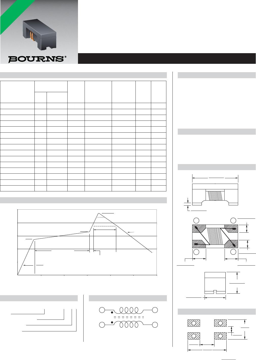
Features
■ High impedance value
■ Current rating up to 400 mA
■ RoHS compliant* and halogen free**
Applications
■ Noise suppression
■ Personal computers
■ Display panels
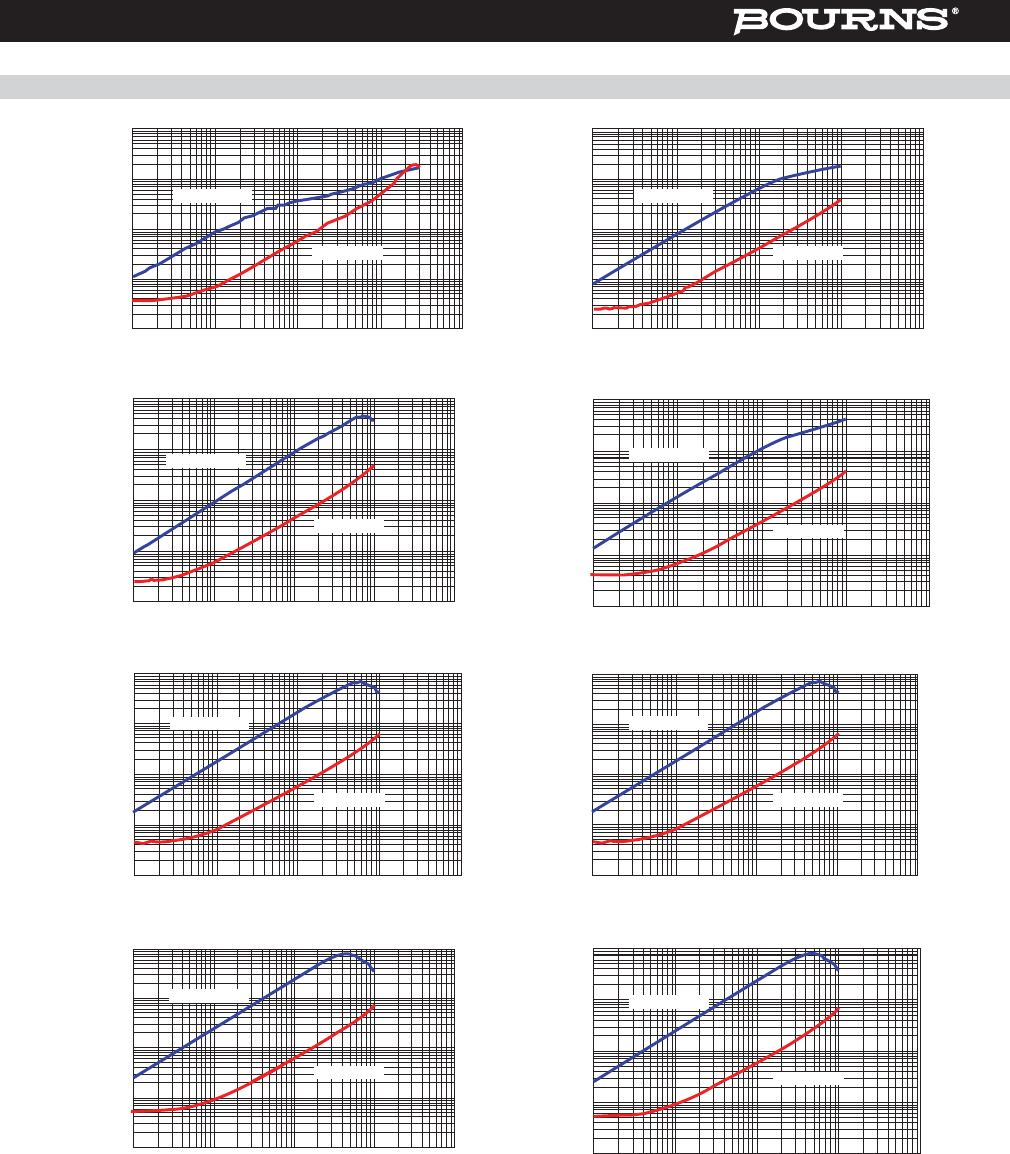
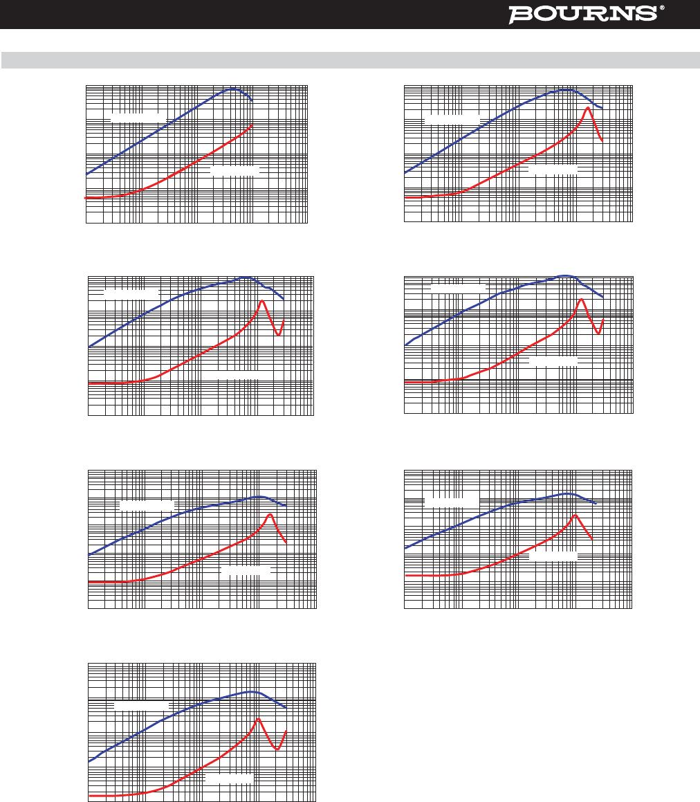
SRF2012A Series - Common Mode Chip Inductors
* RoHS Directive 2002/95/EC Jan. 27, 2003 including annex and RoHS Recast 2011/65/EU June 8, 2011.
** Bourns considers a product to be “halogen free” if (a) the Bromine (Br) content is 900 ppm or less;
(b) the Chlorine (Cl) content is 900 ppm or less; and (c) the total Bromine (Br) and Chlorine (Cl) content is 1500 ppm or less.
Specifi cations are subject to change without notice.
The device characteristics and parameters in this data sheet can and do vary in different applications and actual device performance may vary over time.
Users should verify actual device performance in their specifi c applications.
Refl ow soldering .... 230 °C; 50 sec max.
Operating Temperature
................................-55 °C to +125 °C
(Temperature rise included)
Storage Temperature
................................-55 °C to +125 °C
Resistance to Soldering Heat
.......................... 260 °C, 10 sec. max.
Temperature Rise ......30 °C max. at IDC
Electrical Specifi cations
Part Number
Impedance
@ 100 MHz
Rated
Voltage
(VDC)
Withstanding
Voltage
(DC)
Insulation
Resistance
(MΩ) Min.
DCR
Max.
(Ω)
IDC
Max.
(mA)(Ω)
Tolerance
(%)
SRF2012-300YA 30 ±25 50 125 10 0.20 400
SRF2012-670YA 67 ±25 50 125 10 0.25 400
SRF2012-900YA 90 ±25 50 125 10 0.30 400
SRF2012-121YA 120 ±25 50 125 10 0.30 400
SRF2012-161YA 160 ±25 50 125 10 0.35 350
SRF2012-181YA 180 ±25 50 125 10 0.35 350
SRF2012-201YA 200 ±25 50 125 10 0.40 300
SRF2012-221YA 220 ±25 50 125 10 0.40 300
SRF2012-261YA 260 ±25 50 125 10 0.40 300
SRF2012-301YA 300 ±25 50 125 10 0.50 300
SRF2012-361YA 360 ±25 50 125 10 0.50 300
SRF2012-371YA 370 ±25 50 125 10 0.50 300
SRF2012-501YA 500 ±25 50 125 10 0.50 300
SRF2012-671YA 670 ±25 50 125 10 0.60 140
SRF2012-901YA 900 ±25 50 125 10 0.88 100
General Specifi cations
Core ..............................................Ferrite
Wire ............................Enameled copper
Terminal ....................................Ag/Ni/Sn
Packaging ....... 2000 pcs. per 7-inch reel
Materials
Product Dimensions
*RoHS COMPLIANT
Soldering Profi le
Temperature
(°C)
25
75
125
175
225
275
0 50 100 150 200 250 300
Time (seconds)
120 - 150 seconds
60 - 90
seconds
260°C peak
190°C
150°C
220°C
Ramp Down
6°C/second
maximum
<1> 255°C
<1> Maximum of 10 seconds between
+255°C and +260°C
Ramp Up
3°C/second maximum
10 seconds minimum
Rev. 02/22/05
1.25
(.049)
0.45
(.018)
1.1
(.043)
2.6
(.102)
12
4
3
DIMENSIONS:
MM
(INCHES)
Schematic
How to Order
SRF2012 - 201 Y A
Model
Value Code (see table)
Tolerance Code
Model Suffi x
1
4
2
3
Recommended Layout