LM134-LM234-LM334 Application information
7/16
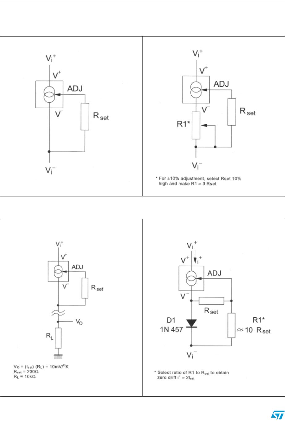
4.6 Sensing temperature
The LM134, LM234, LM334 are excellent remote controlled temperature sensors because
their operation as current sources preserves their accuracy even in the case of long
connecting wires. The output current is directly proportional to the absolute temperature in
Kelvin degrees according to the following equation.
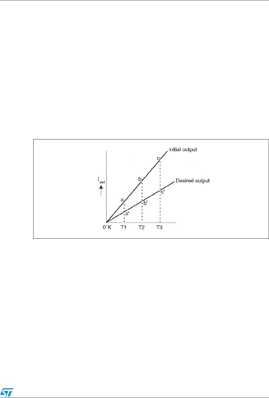
The calibration of the LM134, LM234, LM334 is simplified by the fact that most of the initial
accuracy is due to gain limitation (slope error) and not an offset. Gain adjustment is a one
point trim because the output of the device extrapolates to zero at 0°K.
Figure 10. Device calibration
This particularity of the LM134, LM234, LM334 is illustrated in the above diagram. Line abc
represents the sensor current before adjustment and line a’b’c’ represents the desired
output. A gain adjustment provided at T2 will move the output from b to b’ and will correct
the slope at the same time so that the output at T1 and T3 will be correct. This gain
adjustment can be carried out by means of R
set
or the load resistor used in the circuit. After
adjustment, the slope error should be less than 1%. A low temperature coefficient for R
set
is
necessary to keep this accuracy. A 33ppm/°C temperature drift of R
set
will give an error of
1% on the slope because the resistance follows the same temperature variations as the
LM134, LM234, LM334.
Three wires are required to isolate R
set
from the LM134, LM234, LM334. Since this solution
is not recommended, metal-film resistors with a drift of less than 20ppm/°C are now
available. Wirewound resistors can be used when very high stability is required.
I
set
=
227µV/°K) (T()
R
set
---------------------------------------- -