16
LTC1067/LTC1067-50
APPLICATIONS INFORMATION
WUU
U
This would be used for operating Mode 3. Here, a 0Ω
resistor in the R61 position also works. Jumpers JP52 and
JP62 perform the same functions on the B side of the part.
The buffering amplifier can be configured for inverting or
noninverting operation. For inverting applications, con-
nect jumper JP2 positions 1 and 2. Additionally, connect
jumper JP4 for split supply applications or JP8 for a single
supply. For a noninverting application, connect jumper
JP2 positions 2 and 3.
Several other jumpers should be connected as follows:
JP1: Install a jumper wire from position 1 to position 2,
leave the other positions open.
JP5: Install a jumper wire if split supply, leave open if
single supply.
JP6: Leave open.
JP7: Install a jumper wire.
JP9: Install a jumper wire if single supply, leave open if
split supply.
LTC1067
OR
LTC1067-50
R1
200Ω
1%
CLOCK
IN
C7
0.1µF
C8
0.1µF
C9
10µF
36V
C11
10µF
36V
TP3
TP5
TP6
TP7
TP11
1067 F15
VOA
+
VOA
–
V
OUT
1/2
LT1498
1/2
LT1498
C2, 0.1µF
C1
10µF, 6.3V
JPVNEG
R52
R51
R41
R31
R21
R11
JP1
V
IN
TP4
TP9
TP1
D1
MBR0630T1
TP10
V
+
C3
10µF
16V
1
2
4
3
R
L2
R
B2
R
H2
C13
C10
0.1µF
R4
12
3
3
8
1
4
2
JP52
V
+
NC
V
+
SA
LPA
BPA
HPA/NA
INV A
16
15
14
13
12
11
10
9
CLK
AGND
V
–
SB
LPB
BPB
HPB/NB
INV B
1
2
3
4
5
6
7
8
JP62
CONNECT THIS JUMPER
FOR DUAL SUPPLIES
CONNECT THIS JUMPER
FOR SINGLE SUPPLIES.
THE LTC1067 HAS ON-CHIP
RESISTORS TO GENERATE
1/2 SUPPLY FOR AGND
JPAGND
JP4
JP8
R2
TP2
TP8
V
–
R62
+
C6, 0.1µF
J1
+
–
5
7
6
+
–
R3
C12
C5
C4
10µF
16V
JP3
+
+
JP7
JP9
JP6
JP5
R42
R
L1
R
B1
R
H1
R32
R22
JP51
JP61
R61
+
D2
MBR0630T1
+
JP2
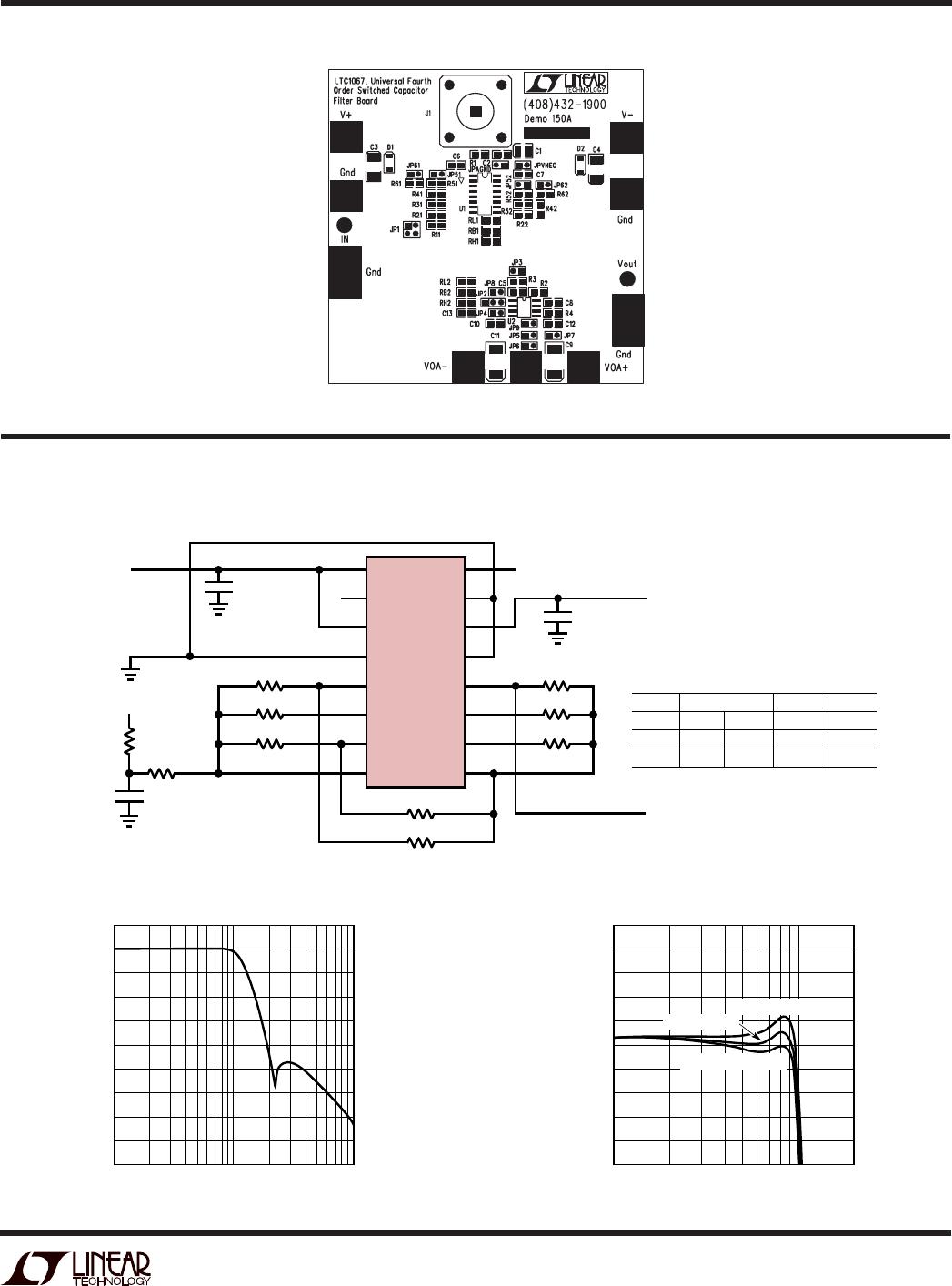
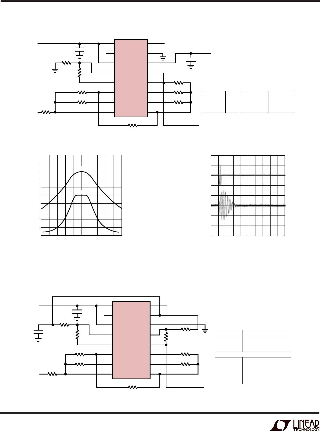
Figure 15. Schematic for the LTC1067/LTC1067-50 Demo Board