VLMS1300, VLMO1300, VLMY1300, VLMG1300, VLMTG1300, VLMB1300, VLMB1310
www.vishay.com
Vishay Semiconductors
Rev. 1.2, 25-Jul-12
1
Document Number: 82437
For technical questions, contact: LED@vishay.com
THIS DOCUMENT IS SUBJECT TO CHANGE WITHOUT NOTICE. THE PRODUCTS DESCRIBED HEREIN AND THIS DOCUMENT
ARE SUBJECT TO SPECIFIC DISCLAIMERS, SET FORTH AT www.vishay.com/doc?91000
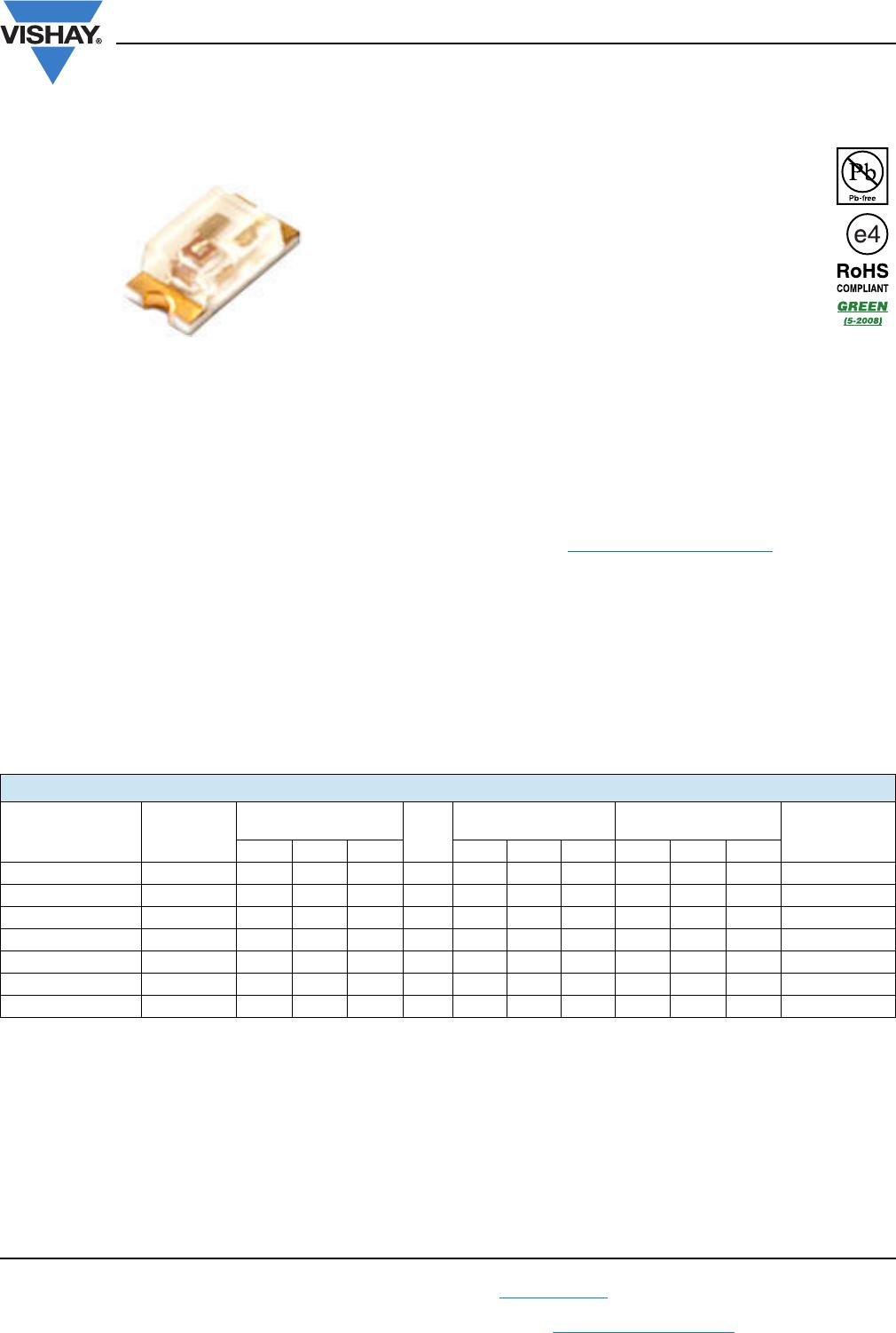
Highbright 0603 ChipLED
DESCRIPTION
The new ChipLED series have been designed in the smallest
SMD package. This innovative ChipLED technology opens
the way to
• smaller products of higher performance
• more design in flexibility
• enhanced applications
The 0603 LED is an obvious solution for small-scale, high
brightness products that are expected to work reliably in an
arduous environment.
PRODUCT GROUP AND PACKAGE DATA
Product group: LED
Package: SMD 0603 ChipLED
Product series: standard
Angle of half intensity: ± 65°
FEATURES
Super thin ChipLED with exceptional brightness
1.6 mm x 0.8 mm x 0.8 mm (L x W x H)
High reliability PCB based
Wavelength (465 to 475) nm (blue), typ. 525 nm
(true green), typ. 571 nm (yellow green), (584.5
to 597) nm (yellow), typ. 605 nm (soft orange),
typ. 631 nm (super red)
InGaN blue available with protection diode,
device type VLMB1310 with HBM 8000 V
AllnGaP and InGaN technology
Viewing angle: extremely wide 130°
Grouping parameter: luminous intensity, wavelength, V
F
Available in 8 mm tape on 7" diameter reel
Compatible to IR reflow soldering
Preconditioning: according to JEDEC level 3
Material categorization: For definitions of compliance
please see www.vishay.com/doc?99912
APPLICATIONS
Backlight keypads
Navigation systems
Cellular phone displays
Displays for industrial control systems
Miniaturized color effects
Traffic displays
PARTS TABLE
PART COLOR
LUMINOUS INTENSITY
(mcd)
at I
F
(mA)
WAVELENGTH
(nm)
FORWARD VOLTAGE
(V)
TECHNOLOGY
MIN. TYP. MAX. MIN. TYP. MAX. MIN. TYP. MAX.
VLMS1300-GS08 Super red 18 54 - 20 - 631 - - 2.0 2.4 AlInGaP
VLMO1300-GS08 Soft orange 45 90 - 20 - 605 - - 2.0 2.4 AlInGaP
VLMY1300-GS08 Yellow 28 - 180 20 584.5 - 597 1.8 - 2.4 AlInGaP
VLMG1300-GS08 Yellow green 18 35 - 20 - 571 - - 2.0 2.4 AlInGaP
VLMTG1300-GS08 True green 71 - 450 20 - 525 - 2.8 3.2 3.6 InGaN
VLMB1300-GS08 Blue 28 - 180 20 465 - 475 2.8 - 3.8 InGaN
VLMB1310-GS08 Blue 28 - 180 20 465 - 475 2.8 - 3.8 InGaN
VLMS1300, VLMO1300, VLMY1300, VLMG1300, VLMTG1300, VLMB1300, VLMB1310
www.vishay.com
Vishay Semiconductors
Rev. 1.2, 25-Jul-12
2
Document Number: 82437
For technical questions, contact: LED@vishay.com
THIS DOCUMENT IS SUBJECT TO CHANGE WITHOUT NOTICE. THE PRODUCTS DESCRIBED HEREIN AND THIS DOCUMENT
ARE SUBJECT TO SPECIFIC DISCLAIMERS, SET FORTH AT www.vishay.com/doc?91000
Note
(1)
Driving the LED in reverse direction is suitable for short term application
ABSOLUTE MAXIMUM RATINGS (T
amb
= 25 °C, unless otherwise specified)
VLMS1300, VLMO1300, VLMY1300, VLMG1300 (AlInGaP technology)
PARAMETER TEST CONDITION SYMBOL VALUE UNIT
Reverse voltage
(1)
V
R
5V
DC forward current I
F
30 mA
Surge forward current 1/10 duty cycle, 0.1 ms pulse width I
FSM
80 mA
Power dissipation T
amb
25 °C P
V
75 mW
Operating temperature range T
amb
- 35 to + 85 °C
Storage temperature range T
stg
- 45 to + 85 °C
IRED solder conditions according Vishay specifications T
st
260 °C
ABSOLUTE MAXIMUM RATINGS (T
amb
= 25 °C, unless otherwise specified)
VLMTG1300, VLMB1300, VLMB1310 (InGaN technology)
PARAMETER TEST CONDITION SYMBOL VALUE UNIT
DC forward current I
F
20 mA
Surge forward current 1/10 duty cycle, 0.1 ms pulse width I
FSM
100 mA
Power dissipation T
amb
25 °C P
V
76 mW
ESD thershold,
for VLMB1310 with protection only
HBM th
ESD HBM
8000 V
Operating temperature range T
amb
- 20 to + 80 °C
Storage temperature range T
stg
- 30 to + 100 °C
IRED solder conditions according Vishay specifications T
st
260 °C
OPTICAL AND ELECTRICAL CHARACTERISTICS (T
amb
= 25 °C, unless otherwise specified)
VLMS1300, SUPER RED
PARAMETER TEST CONDITION SYMBOL MIN. TYP. MAX. UNIT
Luminous intensity I
F
= 20 mA I
V
18 54 - mcd
Dominant wavelength I
F
= 20 mA λ
d
- 631 - nm
Peak wavelength I
F
= 20 mA λ
p
- 639 - nm
Angle of half intensity I
F
= 20 mA ϕ 65- deg
Spectral line half width I
F
= 20 mA Δλ -20-nm
Forward voltage I
F
= 20 mA V
F
-2.02.4V
Junction capacitance V
R
= 0 V, f = 1 MHz C
j
-40-pF
Reverse current V
R
= 5 V I
R
- - 10 μA
OPTICAL AND ELECTRICAL CHARACTERISTICS (T
amb
= 25 °C, unless otherwise specified)
VLMO1300, SOFT ORANGE
PARAMETER TEST CONDITION SYMBOL MIN. TYP. MAX. UNIT
Luminous intensity I
F
= 20 mA I
V
45 90 - mcd
Dominant wavelength I
F
= 20 mA λ
d
- 605 - nm
Peak wavelength I
F
= 20 mA λ
p
- 611 - nm
Angle of half intensity I
F
= 20 mA ϕ 65- deg
Spectral line half width I
F
= 20 mA Δλ -17-nm
Forward voltage I
F
= 20 mA V
F
-2.02.4V
Junction capacitance V
R
= 0 V, f = 1 MHz C
j
-40-pF
Reverse current V
R
= 5 V I
R
- - 10 μA
VLMS1300, VLMO1300, VLMY1300, VLMG1300, VLMTG1300, VLMB1300, VLMB1310
www.vishay.com
Vishay Semiconductors
Rev. 1.2, 25-Jul-12
3
Document Number: 82437
For technical questions, contact: LED@vishay.com
THIS DOCUMENT IS SUBJECT TO CHANGE WITHOUT NOTICE. THE PRODUCTS DESCRIBED HEREIN AND THIS DOCUMENT
ARE SUBJECT TO SPECIFIC DISCLAIMERS, SET FORTH AT www.vishay.com/doc?91000
OPTICAL AND ELECTRICAL CHARACTERISTICS (T
amb
= 25 °C, unless otherwise specified)
VLMY1300, YELLOW
PARAMETER TEST CONDITION SYMBOL MIN. TYP. MAX. UNIT
Luminous intensity I
F
= 20 mA I
V
28 - 180 mcd
Dominant wavelength I
F
= 20 mA λ
d
584.5 - 597 nm
Peak wavelength I
F
= 20 mA λ
p
- 588 - nm
Angle of half intensity I
F
= 20 mA ϕ 65- deg
Spectral line half width I
F
= 20 mA Δλ -15-nm
Forward voltage I
F
= 20 mA V
F
1.8 - 2.4 V
Junction capacitance V
R
= 0 V, f = 1 MHz C
j
-40-pF
Reverse current V
R
= 5 V I
R
- - 10 μA
OPTICAL AND ELECTRICAL CHARACTERISTICS (T
amb
= 25 °C, unless otherwise specified)
VLMG1300, YELLOW GREEN
PARAMETER TEST CONDITION SYMBOL MIN. TYP. MAX. UNIT
Luminous intensity I
F
= 20 mA I
V
18 35 - mcd
Dominant wavelength I
F
= 20 mA λ
d
- 571 - nm
Peak wavelength I
F
= 20 mA λ
p
- 574 - nm
Angle of half intensity I
F
= 20 mA ϕ 65- deg
Spectral line half width I
F
= 20 mA Δλ -15-nm
Forward voltage I
F
= 20 mA V
F
-2.02.4V
Junction capacitance V
R
= 0 V, f = 1 MHz C
j
-40-pF
Reverse current V
R
= 5 V I
R
- - 10 μA
OPTICAL AND ELECTRICAL CHARACTERISTICS (T
amb
= 25 °C, unless otherwise specified)
VLMTG1300, TRUE GREEN
PARAMETER TEST CONDITION SYMBOL MIN. TYP. MAX. UNIT
Luminous intensity I
F
= 20 mA I
V
71 - 450 mcd
Dominant wavelength I
F
= 20 mA λ
d
- 525 - nm
Peak wavelength I
F
= 20 mA λ
p
- 530 - nm
Angle of half intensity I
F
= 20 mA ϕ 65- deg
Spectral line half width I
F
= 20 mA Δλ -35-nm
Forward voltage I
F
= 20 mA V
F
2.8 3.2 3.6 V
Reverse current V
R
= 5 V I
R
- - 10 μA
OPTICAL AND ELECTRICAL CHARACTERISTICS (T
amb
= 25 °C, unless otherwise specified)
VLMB1300, VLMB1310, BLUE
PARAMETER TEST CONDITION SYMBOL MIN. TYP. MAX. UNIT
Luminous intensity I
F
= 20 mA I
V
28 - 180 mcd
Dominant wavelength I
F
= 20 mA λ
d
465 - 475 nm
Peak wavelength I
F
= 20 mA λ
p
- 468 - nm
Angle of half intensity I
F
= 20 mA ϕ 65- deg
Spectral line half width I
F
= 20 mA Δλ -25-nm
Forward voltage I
F
= 20 mA V
F
2.8 - 3.8 V
Reverse current (except VLMB1310) V
R
= 5 V I
R
- - 10 μA
Reverse voltage (VLMB1310 only) I
R
= 10 mA V
R
0.6 - 1.2 V

VLMO1300-GS08

Mfr. #:
Manufacturer:
Description:
Standard LEDs - SMD Soft Orange Clear Non-Diff
Lifecycle:
New from this manufacturer.
Delivery:
DHL FedEx Ups TNT EMS
Payment:
T/T Paypal Visa MoneyGram Western Union