ZL30721 Product Brief
3
Microsemi Corporation
Supported telecom frequencies include PDH, SDH, Synchronous Ethernet, OTN, wireless
Inputs constantly monitored by programmable activity monitors and frequency monitors
Fast activity monitor can disqualify the selected reference after a few missing clock cycles
Frequency measurement and monitoring with 1ppm resolution and accept/reject hysteresis
Optional input clock invalidation on GPIO assertion to react to LOS signals from PHYs
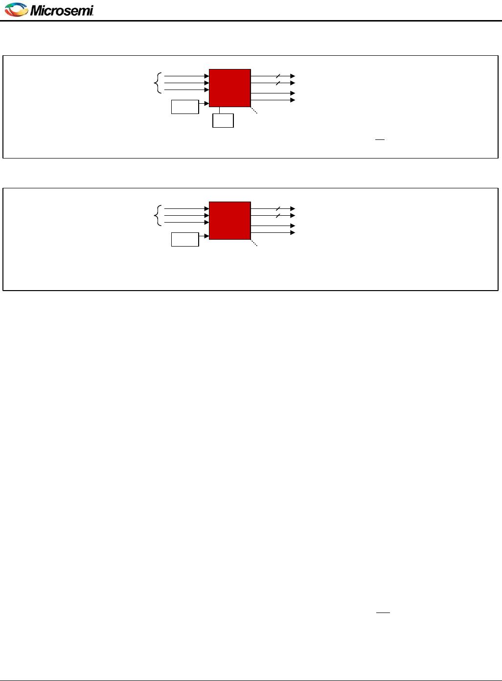
2.4 Electrical Clock Engine Features
Very high-resolution DPLL architecture
State machine automatically transitions between tracking and freerun/holdover states
Revertive or nonrevertive reference selection algorithm
Programmable bandwidth from 0.1Hz to 10Hz
Less than 0.1dB gain peaking
Programmable phase-slope limiting
Programmable tracking range (i.e. hold-in range)
Truly hitless reference switching with <200ps output clock phase transient
o Physical-clock-to-physical-clock reference switching
o Physical-clock-to-packet-timing reference switching
o Packet-timing-to-physical-clock reference switching
o Packet-timing-to-packet-timing reference switching
Support for SyncE and SONET/SDH equipment clock specifications
o ITU-T G.8262 option 1 EEC
o ITU-T G.8262 option 2 EEC
o ITU-T G.813 option 1 SEC
o IUT-T G.813 option 2 SEC
Output phase adjustment in 10ps steps
High-resolution frequency and phase measurement
Fast detection of input clock failure and transition to holdover mode
Holdover frequency averaging with programmable averaging time and delay time
2.5 APLL Features
Very high-resolution fractional scaling (i.e. non-integer multiplication)
Any-to-any frequency conversion with 0ppm error
Two high-speed dividers (integers 4 to 15, half divides 4.5 to 7.5)
Easy-to-configure, completely encapsulated design requires no external VCXO or loop filter
components
2.6 Output Clock Features
Three low-jitter output clocks
Each output can be one differential output or two CMOS outputs
Output clocks can be any frequency from 1Hz to 1035MHz (250MHz max for CMOS and HSTL outputs)
Output jitter as low as 0.25ps RMS (12kHz to 20MHz)
In CMOS mode, an additional divider allows the OCxN pin to be an integer divisor of the OCxP pin
(Example 1: OC3P 125MHz, OC3N 25MHz. Example 2: OC2P 25MHz, OC2N 1Hz)
Outputs easily interface with CML, LVDS, LVPECL, HSTL, SSTL, HCSL and CMOS components
Supported telecom frequencies include PDH, SDH, Synchronous Ethernet, OTN
Sophisticated output-to-output phase alignment
Per-output phase adjustment with high resolution and unlimited range
Per-output enable/disable
Per-output glitchless start/stop (stop high or low)
2.7 General Features
SPI or I
2
C serial microprocessor interface
Automatic self-configuration at power-up from internal EEPROM memory; pin control to specify one of
four stored configurations
Numerically controlled oscillator (NCO) mode allows system software to steer DPLL frequency with
resolution better than 0.01ppb