IDT82V3398 PRODUCT BRIEF SYNCHRONOUS ETHERNET WAN PLL AND CLOCK GENERATION FOR IEEE-1588
Pin Description 7 August 1, 2012
MPU_MODE 45
I
pull-down
CMOS
MPU_MODE: Microprocessor Interface Mode Selection
The device supports 2 microprocessor interface modes: I2C and Serial.
During reset, these pins determine the default value of the MPU_SEL_CNFG[0] bit(b0, 7FH)
as follows:
0: I2C mode
1: Serial mode
After reset, these pins are general purpose inputs. The microprocessor interface mode is
selected by the MPU_SEL_CNFG[0] bits (b0, 7FH).
After reset de-assertion, wait 10 s for the mode to be active.
The value of this pin is always reflected by the MPU_PIN_STS[0] bits (b0, 02H).
CLKE 49
I/O
pull-down
CMOS
CLKE: SCLK Active Edge Selection
In Serial mode, this pin is an input, it selects the active edge of SCLK to update the SDO:
High - The falling edge;
Low - The rising edge.
See Table 28 for details.
SDI 50
I/O
pull-down
CMOS
SDI: Serial Data Input
In Serial mode, this pin is used as the serial data input. Address and data on this pin are seri-
ally clocked into the device on the rising edge of SCLK.
See Table 28 for details.
SDO / I2C_SDA 59
I/O
pull-down
CMOS
SDO: Serial Data Output
In Serial mode, this pin is used as the serial data output. Data on this pin is serially clocked
out of the device on the active edge of SCLK.
I2C_SDA: Serial Data Input/Output
In I2C mode, this pin is used as the input/output for the serial data.
I2C_AD1 52
I
pull-up
CMOS
I2C_AD1: Device Address Bit 1
In I2C mode, I2C_AD[2:0] pins are the address bus of the microprocessor interface.
In Serial mode, this pin should be connected to ground.
I2C_AD2 53
I
pull-up
CMOS
I2C_AD2: Device Address Bit 2
In I2C mode, I2C_AD[2:0] pins are the address bus of the microprocessor interface.
In Serial mode, this pin should be connected to ground.
SCLK / I2C_SCL 54
I
pull-down
CMOS
SCLK: Shift Clock
In Serial mode, a shift clock is input on this pin.
Data on SDI is sampled by the device on the rising edge of SCLK. Data on SDO is updated
on the active edge of SCLK. The active edge is determined by the CLKE.
I2C_SCL: Serial Clock Line
In I2C mode, the serial clock is input on this pin.
JTAG (per IEEE 1149.1)
TRST 44
I
pull-down
CMOS
TRST: JTAG Test Reset (Active Low)
A low signal on this pin resets the JTAG test port.
This pin should be connected to ground when JTAG is not used.
TMS 48
I
pull-up
CMOS
TMS: JTAG Test Mode Select
The signal on this pin controls the JTAG test performance and is sampled on the rising edge
of TCK.
TCK 56
I
pull-down
CMOS
TCK: JTAG Test Clock
The clock for the JTAG test is input on this pin. TDI and TMS are sampled on the rising edge
of TCK and TDO is updated on the falling edge of TCK.
If TCK is idle at a low level, all stored-state devices contained in the test logic will indefinitely
retain their state.
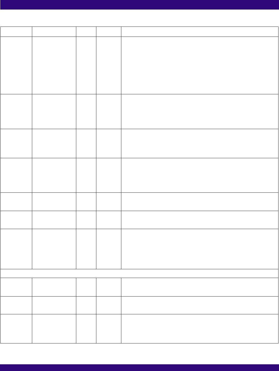
Table 1: Pin Description (Continued)
Name Pin No. I/O Type
Description
1, 2

