CRCW06039M53FKTA

www.vishay.com For technical questions, contact: thickfilmchip@vishay.com
Document Number: 20008
118 Revision: 18-Nov-10
D/CRCW
Vishay
Lead (Pb)-Bearing Thick Film, Rectangular Chip Resistors
FEATURES
Stability ΔR/R = 1 % for 1000 h at 70 °C
Lead (Pb)-bearing termination plating on Ni barrier layer
Metal glaze on high quality ceramic
Halogen-free according to IEC 61249-2-21 definiton
AEC-Q200 qualified, rev. C compliant
Notes
These resistors do not feature a limited lifetime when operated within the permissible limits. However, resistance value drift increasing over
operating time may result in exceeding a limit acceptable to the specific application, thereby establishing a functional lifetime.
Marking: See datasheet “Surface Mount Resistor Marking” (document number 20020).
Power rating depends on the max. temperature at the solder point, the component placement density and the substrate material.
STANDARD ELECTRICAL SPECIFICATIONS
MODEL
SIZE
RATED DISSIPATION
P
70
W
LIMITING
ELEMENT
VOLTAGE
U
max.
AC/DC
TEMPERATURE
COEFFICIENT
ppm/K
TOLERANCE
%
RESISTANCE
RANGE
Ω
SERIES
INCH METRIC
D10/CRCW0402 0402 RR 1005M
0.063 50
± 100
± 200
± 1
± 5
1R0 to 10M
E24; E96
E24
Zero-Ohm-Resistor: R
max.
= 20 mΩ, I
max.
= 1.5 A
D11/CRCW0603 0603 RR 1608M
0.10 75
± 100
± 200
± 1
± 5
1R0 to 10M
E24; E96
E24
Zero-Ohm-Resistor: R
max.
= 20 mΩ, I
max.
= 2.0 A
D12/CRCW0805 0805 RR 2012M
0.125 150
± 100
± 200
± 1
± 5
1R0 to 10M
E24; E96
E24
Zero-Ohm-Resistor: R
max.
= 20 mΩ, I
max.
= 2.5 A
D25/CRCW1206 1206 RR 3216M
0.25 200
± 100
± 200
± 1
± 5
1R0 to 10M
E24; E96
E24
Zero-Ohm-Resistor: R
max.
= 20 mΩ, I
max.
= 3.5 A
CRCW1210 1210 RR 3225M
0.50 200
± 100
± 200
± 1
± 5
1R0 to 10M
E24; E96
E24
Zero-Ohm-Resistor: R
max.
= 20 mΩ, I
max.
= 5.0 A
CRCW1218 1218 RR 3246M
1.0 200
± 100
± 200
± 1
± 5
1R0 to 2M2
E24; E96
E24
Zero-Ohm-Resistor: R
max.
= 20 mΩ, I
max.
= 7.0 A
CRCW2010 2010 RR 5025M
0.75 400
± 100
± 200
± 1
± 5
1R0 to 10M
E24; E96
E24
Zero-Ohm-Resistor: R
max.
= 20 mΩ, I
max.
= 6.0 A
CRCW2512 2512 RR 6332M
1.0 500
± 100
± 200
± 1
± 5
1R0 to 10M
E24; E96
E24
Zero-Ohm-Resistor: R
max.
= 20 mΩ, I
max.
= 7.0 A
Document Number: 20008 For technical questions, contact: thickfilmchip@vishay.com
www.vishay.com
Revision: 18-Nov-10 119
D/CRCW
Lead (Pb)-Bearing Thick Film, Rectangular Chip Resistors
Vishay
Note
(1)
The power dissipation on the resistor generates a temperature rise against the local ambient, depending on the heat flow support of the
printed-circuit board (thermal resistance). The rated dissipation applies only if the permitted film temperature of 155 °C is not exceeded.
Note
(2)
Preferred way for ordering products is by use of the PART NUMBER.
TECHNICAL SPECIFICATIONS
PARAMETER UNIT
D10/
CRCW0402
D11/
CRCW0603
D12/
CRCW0805
D25/
CRCW1206
CRCW1210 CRCW1218 CRCW2010 CRCW2512
Rated dissipation at 70 °C
(1)
W 0.063 0.1 0.125 0.25 0.5 1.0 0.75 1.0
Limiting element voltage
U
MAX.
AC/DC
V 50 75 150 200 200 200 400 500
Insulation voltage
U
INS.
(1 min)
V > 75 > 100 > 200 > 300 > 300 > 300 > 300 > 300
Insulation resistance
Ω
> 10
9
Category temperature range °C - 55 to + 155
Failure rate h
-1
< 0.1 x 10
-9
Weight mg 0.65 2 5.5 10 16 29.5 25.5 40.5
PART NUMBER AND PRODUCT DESCRIPTION
Part Number: CRCW0805562RFKTA
(2)
MODEL VALUE TOLERANCE TCR PACKAGING SPECIAL
CRCW0402
CRCW0603
CRCW0805
CRCW1206
CRCW1210
CRCW1218
CRCW2010
CRCW2512
R = Decimal
K = Thousand
M = Million
0000 = Jumper
F = ± 1 %
J = ± 5 %
Z = Jumper
K = ± 100 ppm/K
N = ± 200 ppm/K
S = Jumper or
special
TA
TB
TC
TD
TE
TF
TG
TH
TK
Up to 2 digits
Product Description: CRCW0805 100 562R 1 % RT1
CRCW0805 100 562R 1 % RT1
MODEL
TCR
RESISTANCE VALUE TOLERANCE
PACK AG IN G
CRCW0402
CRCW0603
CRCW0805
CRCW1206
CRCW1210
CRCW1218
CRCW2010
CRCW2512
± 100 ppm/K
± 200 ppm/K
10R = 10 Ω
562R = 562 Ω
10K = 10.0 kΩ
1M = 1 MΩ
0R0 = Jumper
± 1 %
± 5 %
RT1
RT5
RT6
RT7
RF4
R02
R67
R82
RT9
C R C W 0 8 0 5 5 6 2 R F K T A
www.vishay.com For technical questions, contact: thickfilmchip@vishay.com Document Number: 20008
120 Revision: 18-Nov-10
D/CRCW
Vishay
Lead (Pb)-Bearing Thick Film, Rectangular Chip Resistors
DIMENSIONS
PACKAGING
MODEL UNIT
PAPER TAPE
ACC. IEC 60286-3, TYPE I
BLISTER TAPE
ACC. IEC 60286-3, TYPE II
QUANTITY PART NUMBER PRODUCT DESC. QUANTITY PART NUMBER PRODUCT DESC.
D10/CRCW0402
180 mm/7" 10 000 TD RT7
330 mm/13" 50 000 TE RF4
D11/CRCW0603
180 mm/7" 5000 TA RT1
285 mm/11.25" 10 000 TB RT5
330 mm/13" 20 000 TC RT6
D12/CRCW0805
180 mm/7" 5000 TA RT1
285 mm/11.25" 10 000 TB RT5
330 mm/13" 20 000 TC RT6
D25/CRCW1206
180 mm/7" 5000 TA RT1
285 mm/11.25" 10 000 TB RT5
330 mm/13" 20 000 TC RT6
CRCW1210
180 mm/7" 5000 TA RT1
285 mm/11.25" 10 000 TB RT5
330 mm/13" 20 000 TC RT6
CRCW1218 180 mm/7" 4000 TK RT9
CRCW2010 180 mm/7" 4000 TF R02
CRCW2512 180 mm/7"
2000 TG R67
4000 TH R82
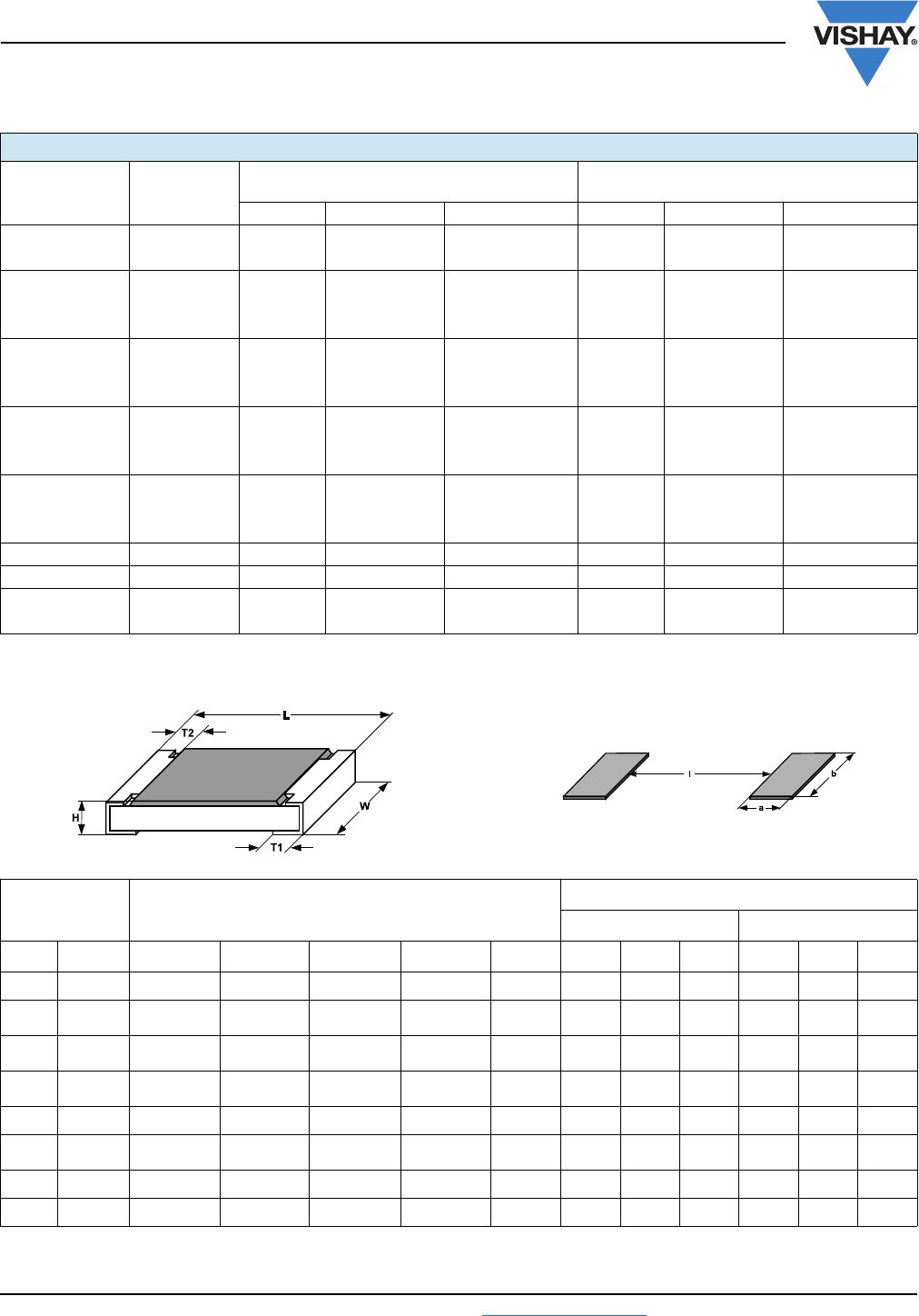
SIZE DIMENSIONS in millimeters
SOLDER PAD DIMENSIONS in millimeters
REFLOW SOLDERING
WAVE SOLDERING
INCH METRIC L W H T1 T2
abl ab l
0402 1005 1.0 ± 0.05 0.5 ± 0.05 0.35 ± 0.05 0.25 ± 0.05 0.2 ± 0.1 0.4 0.6 0.5
0603 1608 1.55
+ 0.10
- 0.05
0.85 ± 0.1 0.45 ± 0.05 0.3 ± 0.2 0.3 ± 0.2 0.5 0.9 1.0 0.9 0.9 1.0
0805 2012 2.0
+ 0.20
- 0.10
1.25 ± 0.15 0.45 ± 0.05 0.3
+ 0.20
- 0.10
0.3 ± 0.2 0.7 1.3 1.2 0.9 1.3 1.3
1206 3216 3.2
+ 0.10
- 0.20
1.6 ± 0.15 0.55 ± 0.05 0.45 ± 0.2 0.4 ± 0.2 0.9 1.7 2.0 1.1 1.7 2.3
1210 3225 3.2 ± 0.2 2.5 ± 0.2 0.55 ± 0.05 0.45 ± 0.2 0.4 ± 0.2 0.9 2.5 2.0 1.1 2.5 2.2
1218 3246 3.2
+ 0.10
- 0.20
4.6 ± 0.15 0.55 ± 0.05 0.45 ± 0.2 0.4 ± 0.2 1.05 4.9 1.9 1.25 4.8 1.9
2010 5025 5.0 ± 0.15 2.5 ± 0.15 0.6 ± 0.1 0.6 ± 0.2 0.6 ± 0.2 1.0 2.5 3.9 1.2 2.5 3.9
2512 6332 6.3 ± 0.2 3.15 ± 0.15 0.6 ± 0.1 0.6 ± 0.2 0.6 ± 0.2 1.0 3.2 5.2 1.2 3.2 5.2

CRCW06039M53FKTA

Mfr. #:
Manufacturer:
Vishay / Dale
Description:
Thick Film Resistors - SMD
Lifecycle:
New from this manufacturer.
Delivery:
DHL FedEx Ups TNT EMS
Payment:
T/T Paypal Visa MoneyGram Western Union