®
1/8
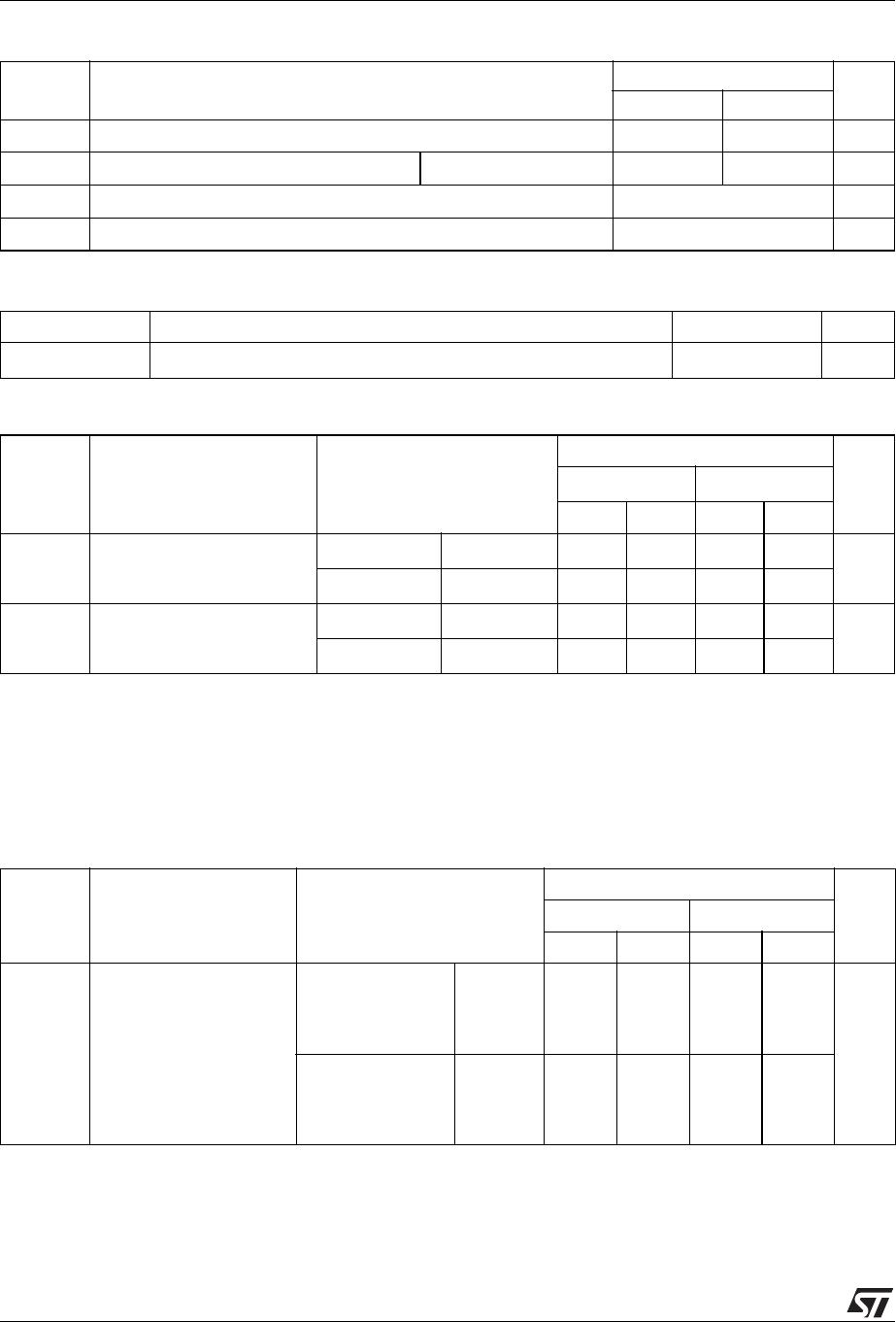
Table 1: Main Product Characteristics
DAMPER MODUL.
I
F(AV)
6 A 3 A
V
RRM
1500 V 600 V
t
rr
(max) 125 ns 50 ns
V
F
(max) 1.7 V 1.4 V
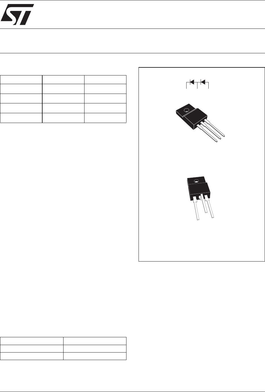
DMV1500H
DAMPER + MODULATION DIODE FOR VIDEO
1
2
3
TO-220FPAB
DMV1500HFD
DAMPER
123
MODULATION
1
2
3
TO-220FPAB F5 Bending
DMV1500HFD5
(optional)
September 2004 REV. 1
FEATURES AND BENEFITS
■ Full kit in one package
■ High breakdown voltage capability
■ Very fast recovery diode
■ Specified turn on switching characteristics
■ Low static and peak forward voltage drop for
low dissipation
■ Insulated version:
Insulated voltage = 2000 V
RMS
Capacitance = 7 pF
■ Planar technology allowing high quality and
best electrical characteristics
■ Outstanding performance of well proven DTV
as damper and new faster Turbo 2 600V
technology as modulation
DESCRIPTION
High voltage semiconductor especially designed
for horizontal deflection stage in standard and high
resolution video display with E/W correction.
The insulated TO-220FPAB package includes
both the DAMPER diode and the MODULATION
diode, thanks to a dedicated design.
Assembled on automated line, it offers very low
dispersion values on insulating and thermal
performanes.
Order Codes
Part Number Marking
DMV1500HFD DMV1500H
DMV1500HFD5 DMV1500H