MKT1817
www.vishay.com
Vishay Roederstein
Not Recommended for New Designs, Use MKT370
Revision: 19-Aug-15
4
Document Number: 26032
For technical questions, contact: dc-film@vishay.com
THIS DOCUMENT IS SUBJECT TO CHANGE WITHOUT NOTICE. THE PRODUCTS DESCRIBED HEREIN AND THIS DOCUMENT
ARE SUBJECT TO SPECIFIC DISCLAIMERS, SET FORTH AT www.vishay.com/doc?91000
MOUNTING
Normal Use
The capacitors are designed for mounting on printed-circuit boards. The capacitors packed in bandoliers are designed for
mounting in printed-circuit boards by means of automatic insertion machines.
For detailed tape specifications refer to packaging information www.vishay.com/docs?28139
Specific Method of Mounting to Withstand Vibration and Shock
In order to withstand vibration and shock tests, it must be ensured that the stand-off pips are in good contact with the
printed-circuit board.
For pitches 15 mm the capacitors shall be mechanically fixed by the leads
For larger pitches the capacitors shall be mounted in the same way and the body clamped
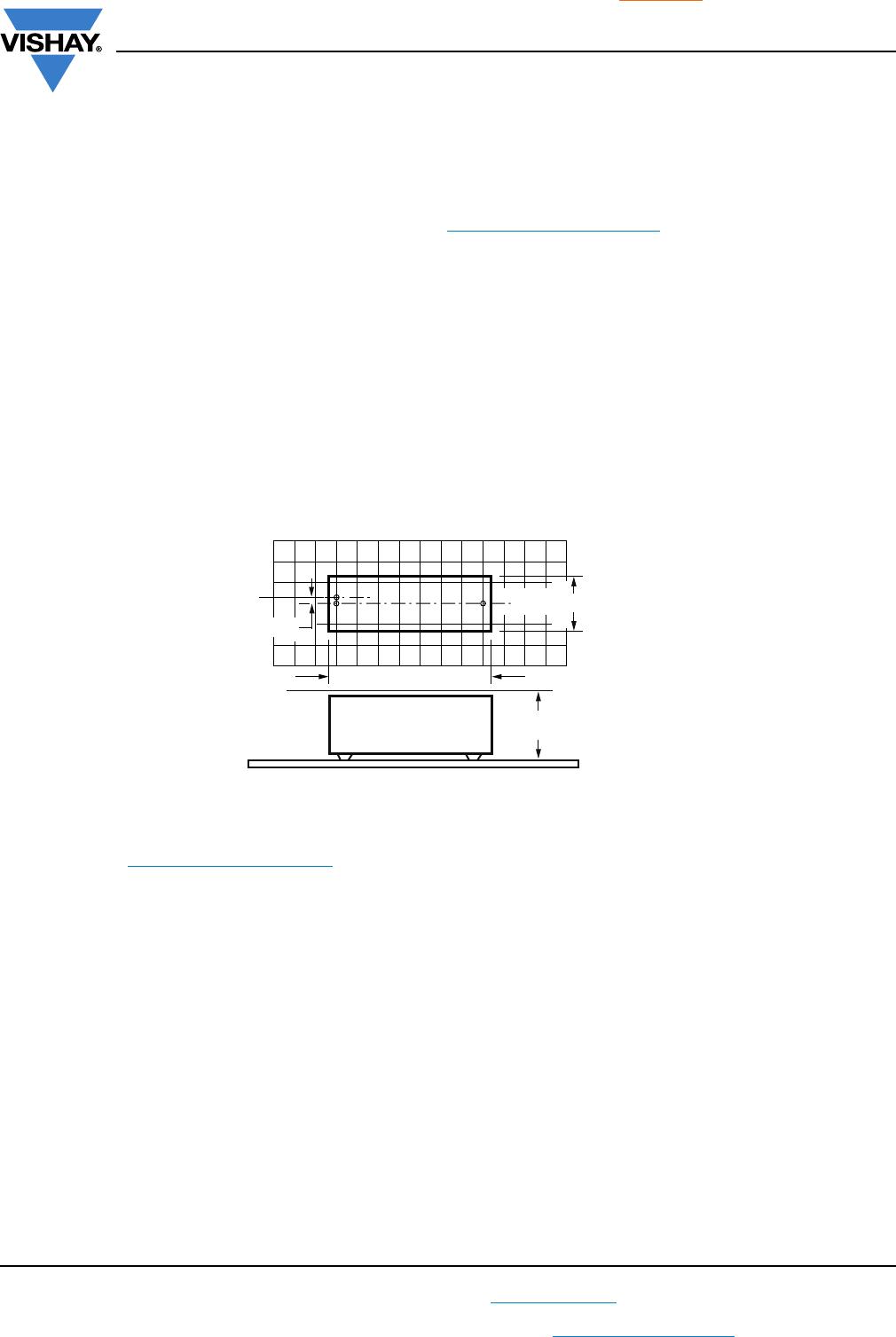
Space Requirements on Printed-Circuit Board
The maximum space for length (I
max.
), width (w
max.
) and height (h
max.
) of film capacitors to take in account on the printed-circuit
board is shown in the drawings.
For products with pitch 15 mm, w = l = 0.3 mm; h = 0.1 mm
Eccentricity defined as in drawing. The maximum eccentricity is smaller than or equal to the lead diameter of the product
concerned.
SOLDERING CONDITIONS
For general soldering conditions and wave soldering profile, we refer to the document “Characteristics and Definitions Used for
Film Capacitors”: www.vishay.com/doc?28147
Storage Temperature
T
stg
= -25 °C to +35 °C with RH maximum 75 % without condensation
Ratings and Characteristics Reference Conditions
Unless otherwise specified, all electrical values apply to an ambient free air temperature of 23 °C ± 1 °C, an atmospheric
pressure of 86 kPa to 106 kPa and a relative humidity of 50 % ± 2 %.
For reference testing, a conditioning period shall be applied over 96 h ± 4 h by heating the products in a circulating air oven at
the rated temperature and a relative humidity not exceeding 20 %.
CBA116
Eccentricity
w
max.
= w + Δw
h
max.
= h + Δh
I
max.
= I + ΔI
Seating plane
MKT1817
www.vishay.com
Vishay Roederstein
Not Recommended for New Designs, Use MKT370
Revision: 19-Aug-15
5
Document Number: 26032
For technical questions, contact: dc-film@vishay.com
THIS DOCUMENT IS SUBJECT TO CHANGE WITHOUT NOTICE. THE PRODUCTS DESCRIBED HEREIN AND THIS DOCUMENT
ARE SUBJECT TO SPECIFIC DISCLAIMERS, SET FORTH AT www.vishay.com/doc?91000
CHARACTERISTICS
Capacitance as a function of ambient temperature
(typical) for voltage 63 V
Capacitance as a function of ambient temperature
(typical) for voltages > 63 V
Capacitance as a function of frequency
(typical curve)
Impedance as a function of frequency
Max. AC voltage as a function of frequency Max. AC voltage as a function of frequency
T
amb
(°C)
a. 63 V series
a
typical
1 kHz
-60
ΔC/C
(%)
6
2
0
-2
-4
-6
4
-20 20 60 100
min.
max.
T
amb
(°C)
b. 100 V series
c. 250 V series
d. 400 V series
typical
1 kHz
- 60
Δ
C/C
(%)
6
2
0
- 2
- 4
- 6
4
- 20 20 60 100
min.
max.
d
c
b
f (Hz)
10
2
10
3
10
4
10
5
ΔC/C
(%)
2
0
- 1
- 2
- 3
1
10
2
10
0
10
- 1
10
- 2
10
- 3
10
1
f (Hz)
10
4
10
6
10
5
10
7
10
8
250 V; 10 nF
63 V; 100 nF
63 V; 1 µF
Impedance
(Ω)
T
amb
≤ 85 °C, 63 V
DC
AC voltage
(V)
10
2
10
1
10
0
f (Hz)
10
1
10
2
10
3
10
4
10
5
56 nF
100 nF
220 nF
1000 nF
10
2
10
1
10
0
f (Hz)
10
3
10
2
10
1
10
4
10
5
AC Voltage
(V)
56 nF
100 nF
220 nF
1000 nF
85 °C < T
amb
≤ 100 °C, 63 V
DC
MKT1817
www.vishay.com
Vishay Roederstein
Not Recommended for New Designs, Use MKT370
Revision: 19-Aug-15
6
Document Number: 26032
For technical questions, contact: dc-film@vishay.com
THIS DOCUMENT IS SUBJECT TO CHANGE WITHOUT NOTICE. THE PRODUCTS DESCRIBED HEREIN AND THIS DOCUMENT
ARE SUBJECT TO SPECIFIC DISCLAIMERS, SET FORTH AT www.vishay.com/doc?91000
Max. AC voltage as a function of frequency Max. AC voltage as a function of frequency
10
2
10
1
10
0
f (Hz)
10
3
10
2
10
1
10
4
10
5
AC Voltage
(V)
330 nF
100 nF
47 nF
12 nF
22 nF
T
amb
≤ 85 °C, 100 V
DC
10
2
10
1
10
0
f (Hz)
10
3
10
2
10
1
10
4
10
5
AC Voltage
(V)
330 nF
100 nF
47 nF
12 nF
22 nF
85 °C < T
amb
≤ 105 °C, 100 V
DC
10
2
10
1
10
0
10
3
f (Hz)
10
3
10
2
10
1
10
4
10
5
AC Voltage
(V)
100 nF
22 nF
10 nF
4.7 nF
47 nF
T
amb
≤ 85 °C, 250 V
DC
10
2
10
1
10
0
10
3
f (Hz)
10
3
10
2
10
1
10
4
10
5
AC Voltage
(V)
85 °C < T
amb
≤ 105 °C, 250 V
DC
100 nF
22 nF
10 nF
4.7 nF
47 nF
10
2
10
1
10
0
10
3
f (Hz)
10
3
10
2
10
1
10
4
10
5
AC Voltage
(V)
10 nF
2.2 nF
4.7 nF
T
amb
≤ 85 °C, 400 V
DC
1.0 nF
33 nF
10
2
10
1
10
0
10
3
f (Hz)
10
3
10
2
10
1
10
4
10
5
AC Voltage
(V)
10 nF
2.2 nF
4.7 nF
85 °C < T
amb
≤ 105 °C, 400 V
DC
1.0 nF
33 nF

MKT1817227256

Mfr. #:
Manufacturer:
Description:
Film Capacitors MKT 2,7 nF 20% 250Vdc 5 mm
Lifecycle:
New from this manufacturer.
Delivery:
DHL FedEx Ups TNT EMS
Payment:
T/T Paypal Visa MoneyGram Western Union