MAX1452
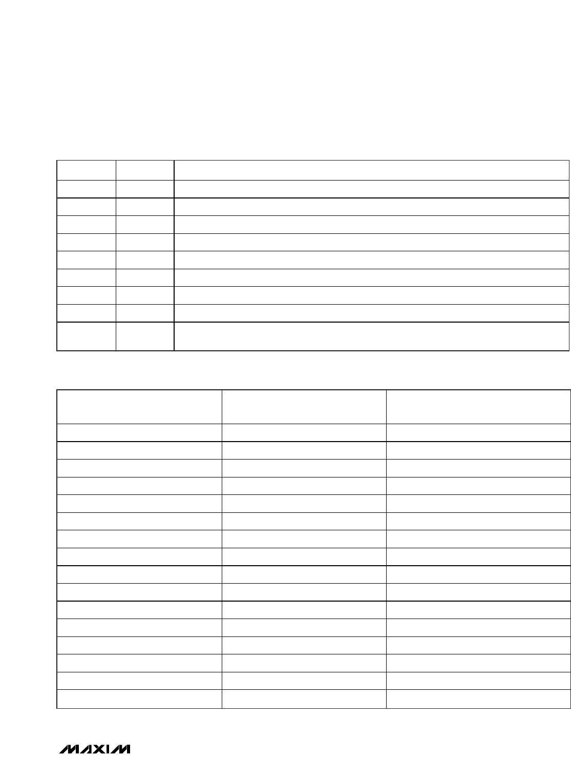
Table 3. Configuration Register (CONFIG[15:0])
FIELD NAME DESCRIPTION
15:13 OSC[2:0] Oscillator frequency setting. Factory preset, do not change.
12 R
EXT
Logic ‘1’ selects external R
ISRC
and R
STC
.
11 CLK1M EN Logic ‘1’ enables CLK1M output driver.
10 PGA Sign Logic ‘1’ inverts INM and INP polarity.
9 IRO Sign Logic ‘1’ for positive input referred offset (IRO). Logic ‘0’ for negative input referred offset (IRO).
8:6 IRO[2:0] Input referred coarse offset adjustment.
5:2 PGA[3:0] Programmable gain amplifier setting.
1 ODAC Sign Logic ‘1’ for positive offset DAC output. Logic ‘0’ for negative offset DAC output.
0
OTCDAC
Sign
Logic ‘1’ for positive offset TC DAC output. Logic ‘0’ for negative offset TC DAC output.
Low-Cost Precision Sensor
Signal Conditioner
______________________________________________________________________________________ 17
Table 4. Input Referred Offset (IRO[2:0])
IRO SIGN, IRO[2:0]
INPUT REFERRED OFFSET
CORRECTION AS % OF VDD
I N PU T R EF ER R ED O F F SET , CO R R EC T IO N
A T VD D = 5 VD C I N mV
1,111 +1.25 +63
1,110 +1.08 +54
1,101 +0.90 +45
1,100 +0.72 +36
1,011 +0.54 +27
1,010 +0.36 +18
1,001 +0.18 +9
1,000 0 0
0,000 0 0
0,001 -0.18 -9
0,010 -0.36 -18
0,011 -0.54 -27
0,100 -0.72 -36
0,101 -0.90 -45
0,110 -1.08 -54
0,111 -1.25 -63

