16
COMMERCIAL AND INDUSTRIAL TEMPERATURE RANGES
IDT72V295/72V2105 3.3V HIGH DENSITY CMOS
SUPERSYNC FIFO
TM
131,072 x 18, 262,144 x 18
Figure 6. Partial Reset Timing
tRS
PRS
tRSR
REN
tRSS
4668 drw 09
tRSR
WEN
tRSS
RT
SEN
tRSS
tRSF
tRSF
OE = HIGH
OE = LOW
PAE
PAF, HF
Q
0 - Qn
tRSF
EF/OR
FF/IR
tRSF
tRSF
If FWFT = HIGH, OR = HIGH
If FWFT = LOW, EF = LOW
If FWFT = LOW, FF = HIGH
If FWFT = HIGH, IR = LOW
tRSS
17
COMMERCIAL AND INDUSTRIAL TEMPERATURE RANGES
IDT72V295/72V2105 3.3V HIGH DENSITY CMOS
SUPERSYNC FIFO
TM
131,072 x 18, 262,144 x 18
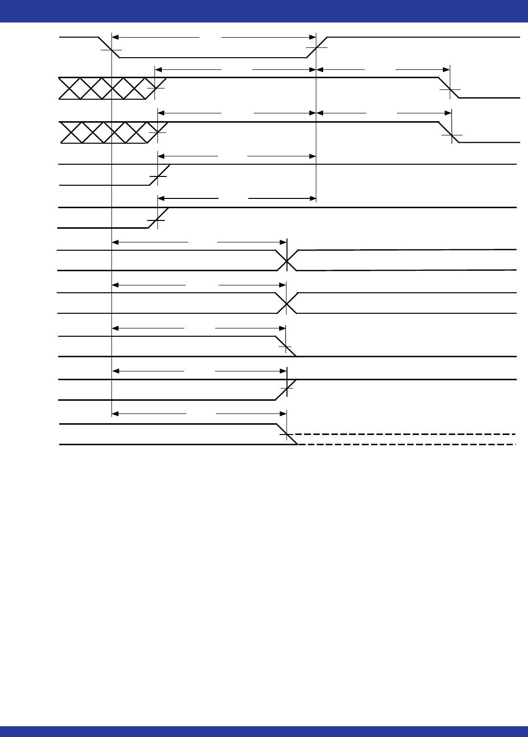
Figure 8. Read Cycle, Empty Flag and First Data Word Latency Timing (IDT Standard Mode)
NOTES:
1. tSKEW1 is the minimum time between a rising WCLK edge and a rising RCLK edge to guarantee that EF will go HIGH (after one RCLK cycle plus tREF). If the time between the rising edge
of WCLK and the rising edge of RCLK is less than tSKEW1, then EF deassertion may be delayed one extra RCLK cycle.
2. LD = HIGH.
3. First word latency: tSKEW1 + 1*TRCLK + tREF.
NOTES:
1. tSKEW1 is the minimum time between a rising RCLK edge and a rising WCLK edge to guarantee that FF will go high (after one WCLK cycle pus tWFF). If the time between the rising
edge of the RCLK and the rising edge of the WCLK is less than tSKEW1, then the FF deassertion may be delayed one extra WCLK cycle.
2. LD = HIGH, OE = LOW, EF = HIGH.
Figure 7. Write Cycle and Full Flag Timing (IDT Standard Mode)
D
0
- D
n
WEN
RCLK
REN
t
ENH
t
ENH
Q
0
- Q
n
DATA READ NEXT DATA READDATA IN OUTPUT REGISTER
t
SKEW1
(1)
4668 drw 10
WCLK
NO WRITE
1
2
1
2
t
DS
NO WRITE
t
WFF
t
WFF
t
WFF
t
A
t
ENS
t
ENS
t
SKEW1
(1)
t
DS
t
A
D
X
t
DH
t
CLK
t
CLKH
t
CLKL
D
X
+1
t
WFF
t
DH
FF
RCLK
REN
4668 drw 11
EF
t
CLK
t
CLKH
t
CLKL
t
ENH
t
REF
t
A
t
OLZ
t
OE
Q
0
- Q
n
OE
WCLK
t
SKEW1
(1)
WEN
D
0
- D
n
t
ENS
t
ENS
t
ENH
t
DS
t
DHS
D
0
1
2
t
OLZ
LAST WORD
D
0
D
1
D
1
t
ENS
t
ENH
t
DS
t
DH
t
OHZ
LAST WORD
t
REF
t
ENH
t
ENS
t
A
t
A
t
REF
t
ENS
t
ENH
NO OPERATION
NO OPERATION
18
COMMERCIAL AND INDUSTRIAL TEMPERATURE RANGES
IDT72V295/72V2105 3.3V HIGH DENSITY CMOS
SUPERSYNC FIFO
TM
131,072 x 18, 262,144 x 18
Figure 9. Write Timing (First Word Fall Through Mode)
NOTES:
1. t
SKEW1 is the minimum time between a rising WCLK edge and a rising RCLK edge to guarantee that OR will go LOW after two RCLK cycles plus tREF. If the time between the rising edge of WCLK and the rising edge of RCLK is less than tSKEW1,
then OR assertion may be delayed one extra RCLK cycle.
2. t
SKEW2 is the minimum time between a rising WCLK edge and a rising RCLK edge to guarantee that PAE will go HIGH after one RCLK cycle plus tPAE. If the time between the rising edge of WCLK and the rising edge of RCLK is less than tSKEW2,
then the PAE deassertion may be delayed one extra RCLK cycle.
3. LD = HIGH, OE = LOW
4. n = PAE offset, m = PAF offset and D = maximum FIFO depth.
5. D = 131,073 for IDT72V295 and 262,145 for IDT72V2105.
6. First word latency: t
SKEW1 + 2*TRCLK + tREF.
W1 W2 W4 W[n +2] W[D-m-1]
W[D-m-2]
W[D-1]
WD
W[n+3]
W[n+4]
W[D-m] W[D-m+1]
WCLK
WEN
D
0 - D17
RCLK
tDH
tDS
tSKEW1
(1)
REN
Q0 - Q17
PAF
HF
PAE
IR
tDS
tDS
tDS
tSKEW2
(2)
tA
tREF
OR
t
PAE
tHF
tWFF
W[D-m+2]
W1
tENH
4668 drw 12
DATA IN OUTPUT REGISTER
W3
1
2
3
1
][
W
][
W
][
W
1
2
tPAF
tENS

72V2105L10PFG

Mfr. #:
Manufacturer:
IDT
Description:
FIFO 256Kx18 3.3V SUPERSYNC FIFO
Lifecycle:
New from this manufacturer.
Delivery:
DHL FedEx Ups TNT EMS
Payment:
T/T Paypal Visa MoneyGram Western Union