ILD755-2

IL755, ILD755
www.vishay.com
Vishay Semiconductors
Rev. 1.6, 02-Dec-11
1
Document Number: 83641
For technical questions, contact: optocoupleranswers@vishay.com
THIS DOCUMENT IS SUBJECT TO CHANGE WITHOUT NOTICE. THE PRODUCTS DESCRIBED HEREIN AND THIS DOCUMENT
ARE SUBJECT TO SPECIFIC DISCLAIMERS, SET FORTH AT www.vishay.com/doc?91000
Optocoupler, Photodarlington Output, AC Input,
High Gain (Single, Dual Channel)
DESCRIPTION
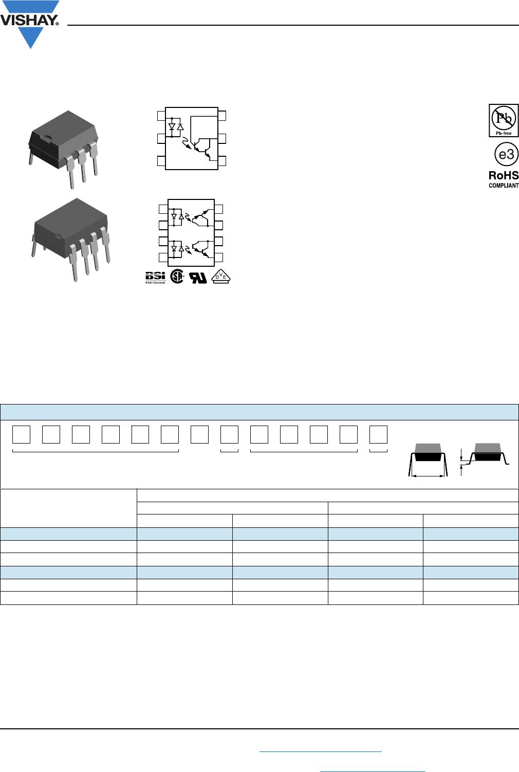
The IL755, ILD755 are bidirectional input optically coupled
isolators. They consist of two gallium arsenide infrared
emitting diodes coupled to a silicon NPN photodarlington
per channel.
The IL755 is single channel Darlington optocoupler. The
ILD755 has two isolated channels in a single DIP package.
FEATURES
AC or polarity insensitive inputs
Built-in reverse polarity input protection
Industry standard DIP package
Compliant to RoHS Directive 2002/95/EC and
in accordance to WEEE 2002/96/EC
APPLICATIONS
Designed for applications requiring detection or
monitoring of AC signals
AGENCY APPROVALS
UL1577, file no. E52744 system code H, double protection
CSA 93751
BSI IEC 60950; IEC 60065
DIN EN 60747-5-2 (VDE 0884)/DIN EN 60747-5-5
(pending), available with option 1
•CQC
Notes
Additional options may be possible, please contact sales office.
(1)
Also available in tubes; do not add “T” to end.
B
C
E
NC
A/C
C/A
1
2
3
6
5
4
E
C
C
E
A
A
1
2
3
4
5
6
7
8
C
C
i179037-1
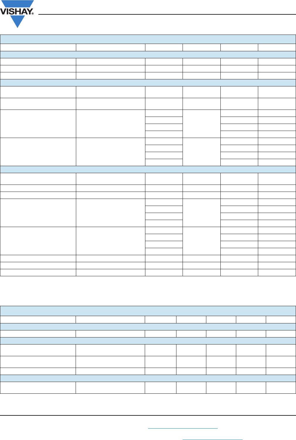
ORDERING INFORMATION
ILx755-#X0##T
PART NUMBER CTR
BIN
PACKAGE OPTION TAPE
AND
REEL
AGENCY CERTIFIED/PACKAGE
CTR (%)
SINGLE CHANNEL, 6 PIN DUAL CHANNEL, 8 PIN
± 2 mA ± 1 mA ± 2 mA ± 1 mA
UL, CSA, BSI, CQC 750 1000 750 1000
DIP-# IL755-1 IL755-2 ILD755-1 ILD755-2
SMD-#, option 7 IL755-1X007T
(1)
IL755-2X007T - ILD755-2X007T
VDE, UL, CSA, BSI, CQC 750 1000 750 1000
DIP-# IL755-1X001 - - -
SMD-#, option 7 - - ILD755-1X017 -
7.62 mm
DIP-#
> 0.7 mm
Option 7
IL755, ILD755
www.vishay.com
Vishay Semiconductors
Rev. 1.6, 02-Dec-11
2
Document Number: 83641
For technical questions, contact: optocoupleranswers@vishay.com
THIS DOCUMENT IS SUBJECT TO CHANGE WITHOUT NOTICE. THE PRODUCTS DESCRIBED HEREIN AND THIS DOCUMENT
ARE SUBJECT TO SPECIFIC DISCLAIMERS, SET FORTH AT www.vishay.com/doc?91000
Note
Stresses in excess of the absolute maximum ratings can cause permanent damage to the device. Functional operation of the device is not
implied at these or any other conditions in excess of those given in the operational sections of this document. Exposure to absolute
maximum ratings for extended periods of the time can adversely affect reliability.
Note
Minimum and maximum values are testing requirements. Typical values are characteristics of the device and are the result of engineering
evaluation. Typical values are for information only and are not part of the testing requirements.
ABSOLUTE MAXIMUM RATINGS (T
amb
= 25 °C, unless otherwise specified)
PARAMETER TEST CONDITION PART SYMBOL VALUE UNIT
INPUT
Forward continuous current I
F
60 mA
Power dissipation P
diss
100 mW
Derate linearly from 25°C 1.33 mW/°C
OUTPUT
Collector emitter breakdown
voltage
BV
CEO
60 V
Collector base breakdown
voltage
BV
CBO
60 V
Power dissipation
IL755-1
P
diss
200 mW
IL755-2 200 mW
ILD755-1 150 mW
ILD755-2 150 mW
Derate linearly from 25°C
IL755-1 2.6 mW/°C
IL755-2 2.6 mW/°C
ILD755-1 2.0 mW/°C
ILD755-2 2.0 mW/°C
COUPLER
Isolation test voltage
between emitter and detector
t = 1 s V
ISO
7500/5300 V
AC peak
/V
RMS
Creepage distance 7mm
Clearance distance 7mm
Total power dissipation
IL755-1
P
tot
250 mW
IL755-2 250 mW
ILD755-1 400 mW
ILD755-2 400 mW
Derate linearly from 25 °C
IL755-1 3.0 mW/°C
IL755-2 3.0 mW/°C
ILD755-1 3.0 mW/°C
ILD755-2 3.0 mW/°C
Storage temperature T
stg
- 55 to + 150 °C
Operating temperature T
amb
- 55 to + 100 °C
Lead soldering time at 260 °C 10 s
ELECTRICAL CHARACTERISTICS (T
amb
= 25 °C, unless otherwise specified)
PARAMETER TEST CONDITION SYMBOL MIN. TYP. MAX. UNIT
INPUT
Forward voltage I
F
= ± 10 mA V
F
1.2 1.5 V
OUTPUT
Collector emitter breakdown
voltage
I
C
= 1.0 mA BV
CEO
60 75 V
Collector base breakdown
voltage
I
C
= 10 μA BV
CBO
60 90 V
Collector emitter leakage current V
CE
= 10 V, I
F
= 0 A I
CEO
10 100 nA
COUPLER
Collector emitter saturation
voltage
I
C
= 10 mA, I
F
= ± 10 mA V
CEsat
1V
IL755, ILD755
www.vishay.com
Vishay Semiconductors
Rev. 1.6, 02-Dec-11
3
Document Number: 83641
For technical questions, contact: optocoupleranswers@vishay.com
THIS DOCUMENT IS SUBJECT TO CHANGE WITHOUT NOTICE. THE PRODUCTS DESCRIBED HEREIN AND THIS DOCUMENT
ARE SUBJECT TO SPECIFIC DISCLAIMERS, SET FORTH AT www.vishay.com/doc?91000
TYPICAL CHARACTERSITICS (T
amb
= 25 °C, unless otherwise specified)
Fig. 1 - LED Forward Current vs. Forward Voltage
Fig. 2 - Normalized Non-Saturated and Saturated CTR
CE
vs.
LED Current
Fig. 3 - Normalized Non-Saturated and Saturated CTR
CE
vs.
LED Current
Fig. 4 - Normalized Non-Saturated and Saturated I
CE
vs.
LED Current
CURRENT TRANSFER RATIO (T
amb
= 25 °C, unless otherwise specified)
PARAMETER TEST CONDITION PART SYMBOL MIN. TYP. MAX. UNIT
Current transfer ratio
I
F
= ± 2 mA, V
CE
= 5.0 V IL755-1 CTR 750 %
I
F
= ± 2 mA, V
CE
= 5.0 V ILD755-1 CTR 750 %
I
F
= ± 1 mA, V
CE
= 5.0 V IL755-2 CTR 1000 %
I
F
= ± 1 mA, V
CE
= 5.0 V ILD755-2 CTR 1000 %
SWITCHING CHARACTERISTICS (T
amb
= 25 °C, unless otherwise specified)
PARAMETER TEST CONDITION PART SYMBOL MIN. TYP. MAX. UNIT
Rise time V
CC
= 10 V, I
F
= ± 2 mA, R
L
= 100 Ω
IL755-1 t
r
50 μs
ILD755-1 t
r
50 μs
Fall time V
CC
= 10 V, I
F
= ± 2 mA, R
L
= 100 Ω
IL755-1 t
f
50 μs
ILD755-1 t
f
50 μs
Rise time V
CC
= 10 V, I
F
= ± 1 mA, R
L
= 100 Ω
IL755-2 t
r
70 μs
ILD755-2 t
r
70 μs
Fall time V
CC
= 10 V, I
F
= ± 1 mA, R
L
= 100 Ω
IL755-2 t
f
70 μs
ILD755-2 t
f
70 μs
iil755b_01
- 1.5 - 1.0 - 0.5 0.0 0.5 1.0 1.5
60
40
20
0
- 20
- 40
- 60
- 55 °C
V
F
- LED Forward Voltage (V)
I
F
- LED Forward Current (mA)
85 °C
25 °C
iil755_02
0.1 1 10 100
I
F
- LED Current (mA)
N
CTRce
- Normalized (CTRce)
0.0
0.5
1.0
1.5
2.0
2.5
3.0
3.5
4.0
V
ce
= 1 V
V
ce
= 5 V
Normalized to:
V
ce
= 5 V
I
F
= 1 mA
iil755_03
1001010.1
0.0
0.5
1.0
1.5
2.0
2.5
3.0
V
ce
= 1 V
V
ce
= 5 V
I
F
- LED Current (mA)
N
CTRce
- Normalized CTRce
Normalized to:
V
ce
= 5 V
I
F
= 2 mA
iil755_04
100
10.1
0.01
0.1
1
10
100
V
ce
= 1 V
V
ce
= 5 V
I
F
- LED Current (mA)
NI
ce
- Normalized (I
ce
)
I
F
= 2 mA
V
ce
= 5 V
10
Normalized to:

ILD755-2

Mfr. #:
Manufacturer:
Vishay Semiconductors
Description:
Transistor Output Optocouplers Photodarlington Out Dual CTR >1000%
Lifecycle:
New from this manufacturer.
Delivery:
DHL FedEx Ups TNT EMS
Payment:
T/T Paypal Visa MoneyGram Western Union