IDT 89HPES24NT24G2 Datasheet
4 of 35 December 17, 2013
SMBus Interface
The PES24NT24G2 contains two SMBus interfaces. The slave interface provides full access to the configuration registers in the PES24NT24G2,
allowing every configuration register in the device to be read or written by an external agent. The master interface allows the default configuration
register values of the PES24NT24G2 to be overridden following a reset with values programmed in an external serial EEPROM. The master interface
is also used by an external Hot-Plug I/O expander.
Each of the two SMBus interfaces contain an SMBus clock pin and an SMBus data pin. In addition, the slave SMBus has SSMBADDR1 and
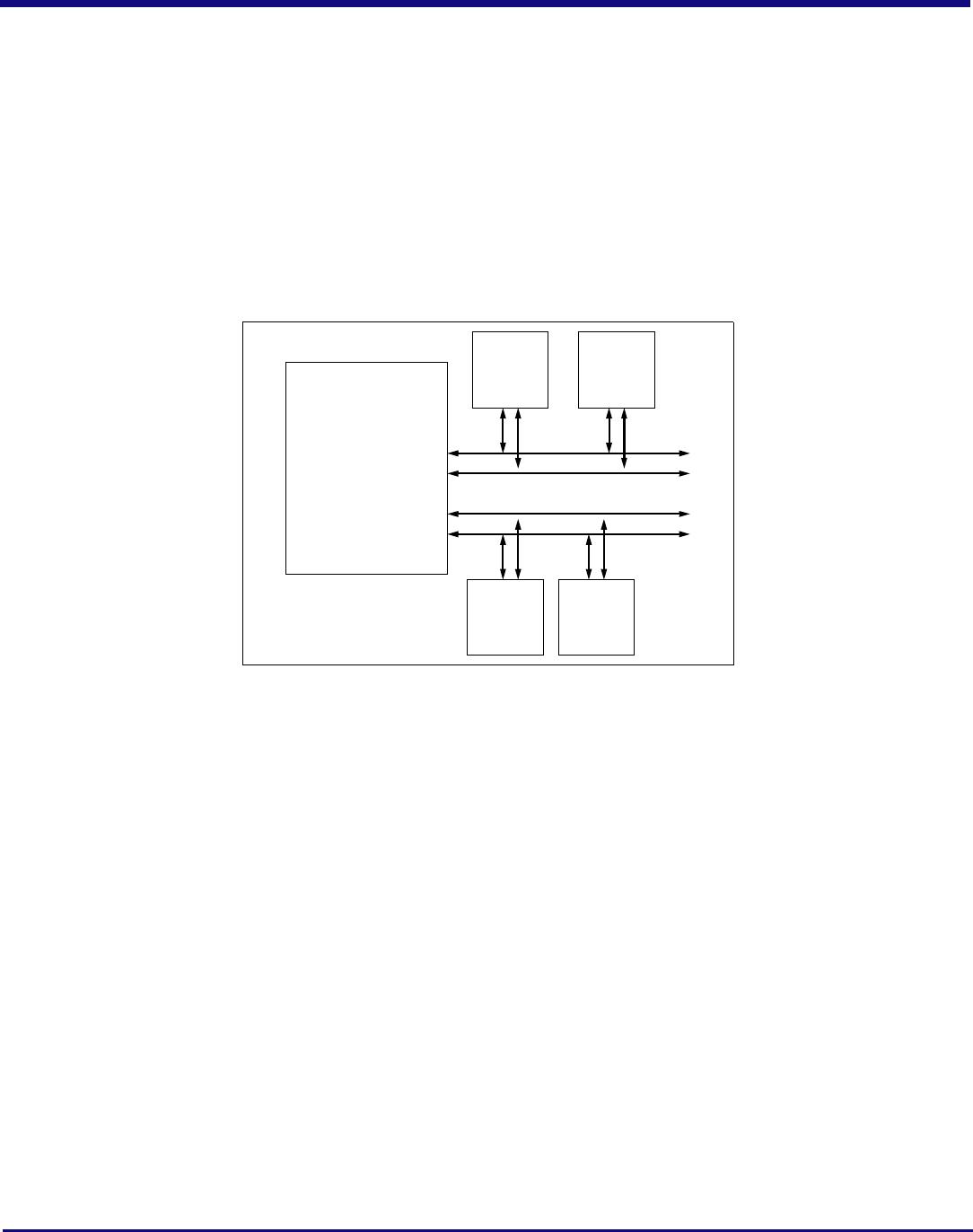
SSMBADDR2 pins. As shown in Figure 2, the master and slave SMBuses may only be used in a split configuration. In the split configuration, the
master and slave SMBuses operate as two independent buses; thus, multi-master arbitration is not required. The SMBus master interface does not
support SMBus arbitration. As a result, the switch’s SMBus master must be the only master in the SMBus lines that connect to the serial EEPROM
and I/O expander slaves.
Figure 2 Split SMBus Interface Configuration
Hot-Plug Interface
The PES24NT24G2 supports PCI Express Hot-Plug on each downstream port (ports 1 through 23). To reduce the number of pins required on the
device, the PES24NT24G2 utilizes an external I/O expander, such as that used on PC motherboards, connected to the SMBus master interface.
Following reset and configuration, whenever the state of a Hot-Plug output needs to be modified, the PES24NT24G2 generates an SMBus transaction
to the I/O expander with the new value of all of the outputs. Whenever a Hot-Plug input changes, the I/O expander generates an interrupt which is
received on the IOEXPINTN input pin (alternate function of GPIO) of the PES24NT24G2. In response to an I/O expander interrupt, the PES24NT24G2
generates an SMBus transaction to read the state of all of the Hot-Plug inputs from the I/O expander.
General Purpose Input/Output
The PES24NT24G2 provides 9 General Purpose I/O (GPIO) pins that may be individually configured as general purpose inputs, general purpose
outputs, or alternate functions. All GPIO pins are shared with other on-chip functions. These alternate functions may be enabled via software, SMBus
slave interface, or serial configuration EEPROM.
Pin Description
The following tables list the functions of the pins provided on the PES24NT24G2. Some of the functions listed may be multiplexed onto the same
pin. The active polarity of a signal is defined using a suffix. Signals ending with an “N” are defined as being active, or asserted, when at a logic zero
(low) level. All other signals (including clocks, buses, and select lines) will be interpreted as being active, or asserted, when at a logic one (high) level.
Differential signals end with a suffix “N” or “P.” The differential signal ending in “P” is the positive portion of the differential pair and the differential signal
ending in “N” is the negative portion of the differential pair.
Note: Pin [x] of a port refers to a lane. For port 0, PE00RN[0] refers to lane 0, PE00RN[1] refers to lane 1, etc.
Processor
Switch
SSMBCLK
SSMBDAT
MSMBCLK
MSMBDAT
SMBus
Master
Other
SMBus
Devices
Serial
EEPROM
...
Hot-Plug
I/O
Expander