ADuM240D/ADuM240E/ADuM241D/ADuM241E/ADuM242D/ADuM242E Data Sheet
Rev. A | Page 6 of 26
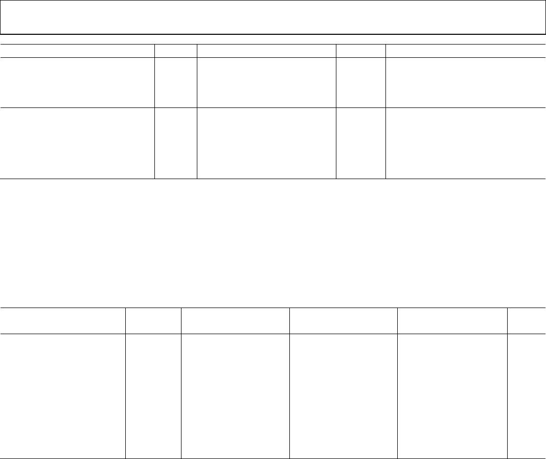
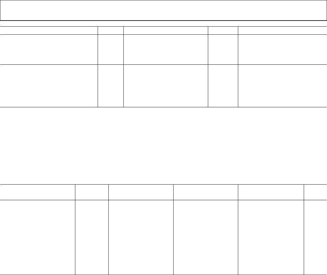
Parameter Symbol Min Typ Max Unit Test Conditions/Comments
Undervoltage Lockout UVLO
Positive V
DDx
Threshold V
DDxUV+
1.6 V
Negative V
DDx
Threshold V
DDxUV−
1.5 V
V
DDx
Hysteresis V
DDxUVH
0.1 V
AC SPECIFICATIONS
Output Rise/Fall Time t
R
/t
F
2.5 ns 10% to 90%
Common-Mode Transient Immunity
7
|CM
H
| 75 100 kV/µs
V
Ix
= V
DDx
, V
CM
= 1000 V,
transient magnitude = 800 V
|CM
L
| 75 100 kV/µs
V
Ix
= 0 V, V
CM
= 1000 V,
transient magnitude = 800 V
1
150 Mbps is the highest data rate that can be guaranteed, although higher data rates are possible.
2
I
Ox
is the Channel x output current, where x = A, B, C, or D.
3
V
IxH
is the input side logic high.
4
V
IxL
is the input side logic low.
5
V
I
is the voltage input.
6
E0 is the ADuM240E0/ADuM241E0/ADuM242E0 models, D0 is the ADuM240D0/ADuM241D0/ADuM242D0 models, E1 is the ADuM240E1/ADuM241E1/ADuM242E1
models, and D1 is the ADuM240D1/ADuM241D1/ADuM242D1 models. See the Ordering Guide section.
7
|CM
H
| is the maximum common-mode voltage slew rate that can be sustained while maintaining the voltage output (V
O
) > 0.8 V
DDx
. |CM
L
| is the maximum common-
mode voltage slew rate that can be sustained while maintaining V
O
> 0.8 V. The common-mode voltage slew rates apply to both rising and falling common-mode
voltage edges.
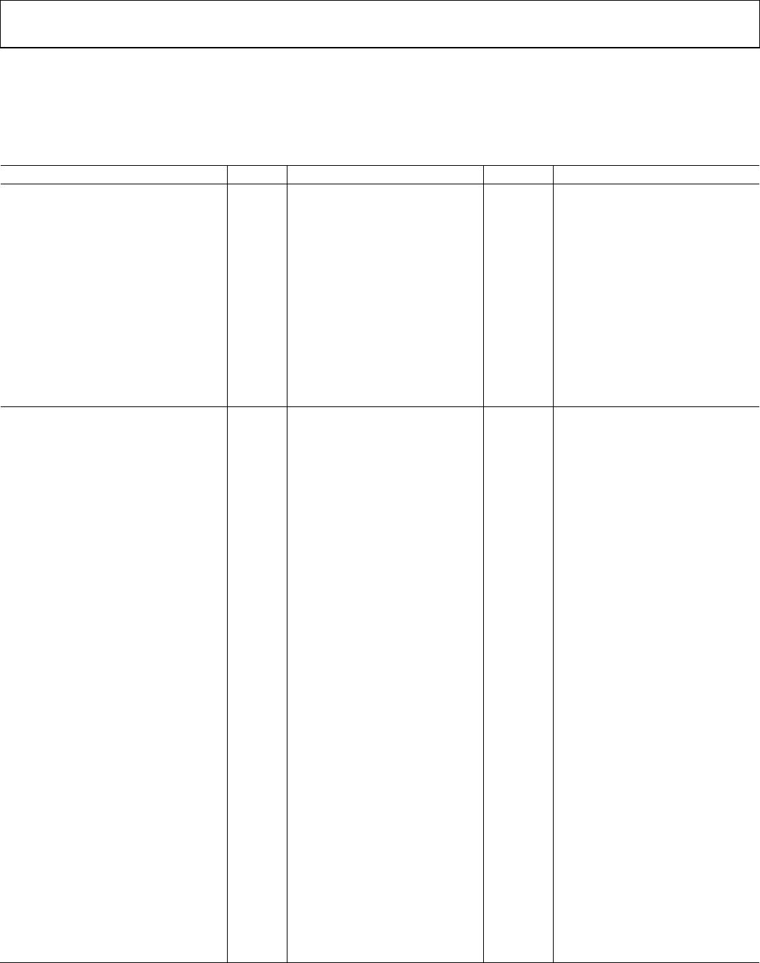
Table 4. Total Supply Current vs. Data Throughput
1 Mbps 25 Mbps 100 Mbps
Parameter Symbol Min Typ Max Min Typ Max Min Typ Max Unit
SUPPLY CURRENT
ADuM240D/ADuM240E
Supply Current Side 1 I
DD1
6.6 9.8 7.4 11.2 10.7 15.9 mA
Supply Current Side 2 I
DD2
2.0 3.7 3.5 5.5 8.2 11.6 mA
ADuM241D/ADuM241E
Supply Current Side 1 I
DD1
5.65 10.1 6.65 10.5 10.4 14.9 mA
Supply Current Side 2 I
DD2
3.9 6.65 5.2 8.0 9.4 12.8 mA
ADuM242D/ADuM242E
Supply Current Side 1 I
DD1
4.3 7.7 5.6 9.0 9.1 13 mA
Supply Current Side 2 I
DD2
5.0 8.4 6.2 9.6 9.8 13.7 mA