Expand menu
Hello, Sign in
My Account
0
Cart
Home
Products
Sensors
Semiconductors
Passive Components
Connectors
Power
Electromechanical
Optoelectronics
Circuit Protection
Integrated Circuits - ICs
Main Products
Manufacturers
Blog
Services
About OMO
About Us
Contact Us
Check Stock
M74HCT540RM13TR
P1-P3
P4-P6
P7-P9
M74HCT
541
4/9
CAPACITIVE CHARA
CT
ERISTI
CS
1)
C
PD
is
d
efined
as the
value of
t
he I
C’s int
ernal eq
uival
ent capa
citan
ce whic
h is calc
ulate
d f
rom
the oper
ating c
urren
t consu
mption
wi
tho
ut
lo
ad. (Re
fer
to Tes
t Circu
it).
Averag
e ope
rating
curr
ent ca
n be o
btaine
d by
t
h
e follo
wing e
quatio
n. I
CC(opr)
= C
PD
x V
CC
x f
IN
+ I
CC
/8 (pe
r circui
t)
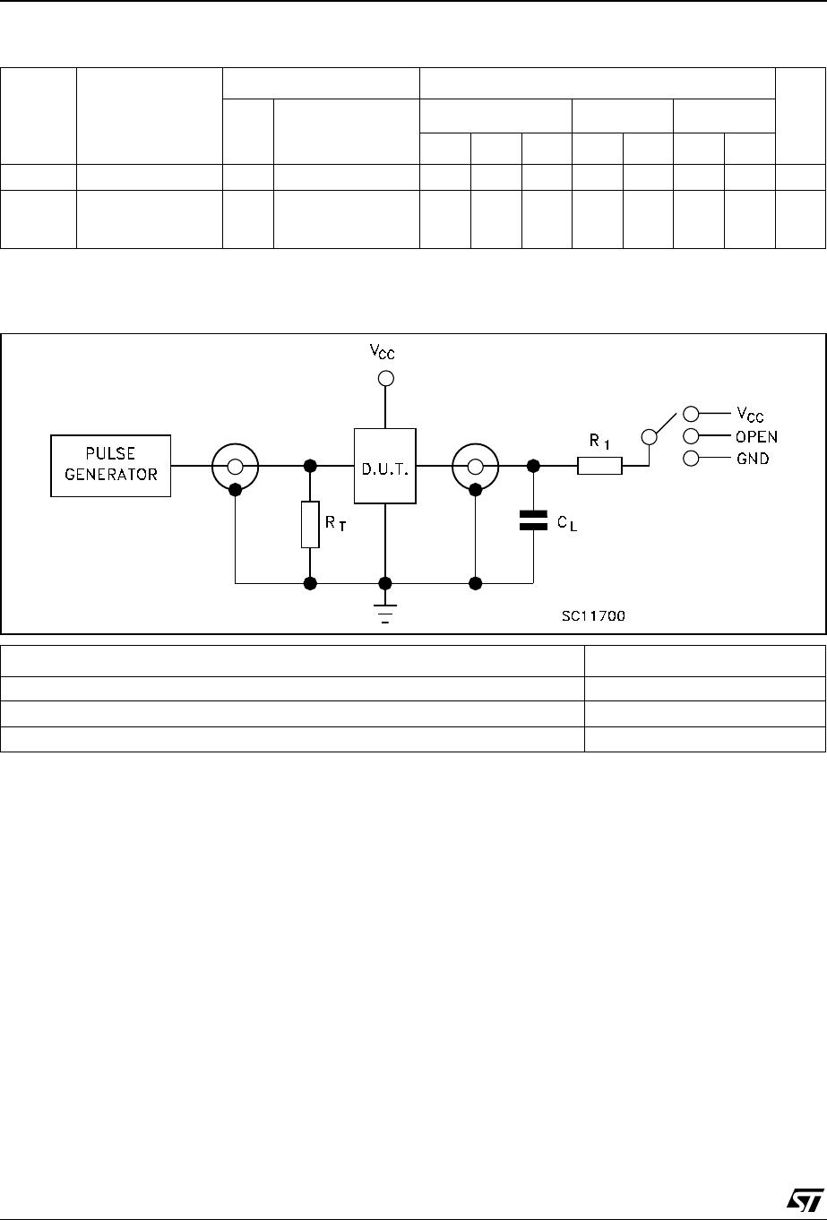
TEST CIRCUIT
C
L
= 50p
F/150pF
or equiv
alent (in
cludes
jig and
pro
be capa
citan
c
e)
R
1
= 1K
Ω
or
equiva
lent
R
T
= Z
OUT
of pu
ls
e genera
t
or (typically 50
Ω
)
Symbo
l
Param
eter
T
est C
ondition
V
alu
e
Unit
V
CC
(V)
T
A
= 25°
C
-40 to 8
5°C
-55 to 1
25°C
Min.
T
yp.
Max.
Min.
Ma
x.
Mi
n.
Max.
C
IN
Input Ca
pacitance
5
.
0
5
1
01
01
0
p
F
C
PD
Power D
issipation
Capacita
nce (note
1)
5.0
34
pF
TEST
SWITCH
t
PL
H
, t
PHL
Open
t
PZL
, t
PLZ
V
CC
t
PZH
, t
PHZ
GND
M7
4H
CT541
5/9
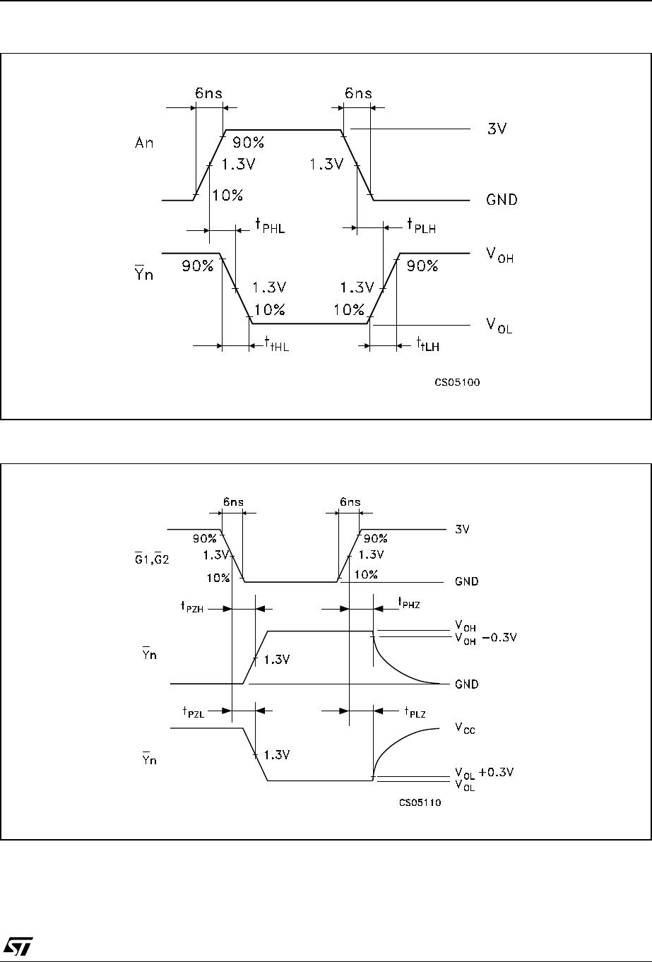
WAVEFORM 1: PROPAGATION DELAY
TIMES
(f=1
MHz; 5
0% duty
cycle)
WAV
E
FORM
2 : OUTPUT ENABLE
AND DISABLE TIMES
(f=1
MHz; 5
0% du
ty
cycle
)
M74HCT
541
6/9
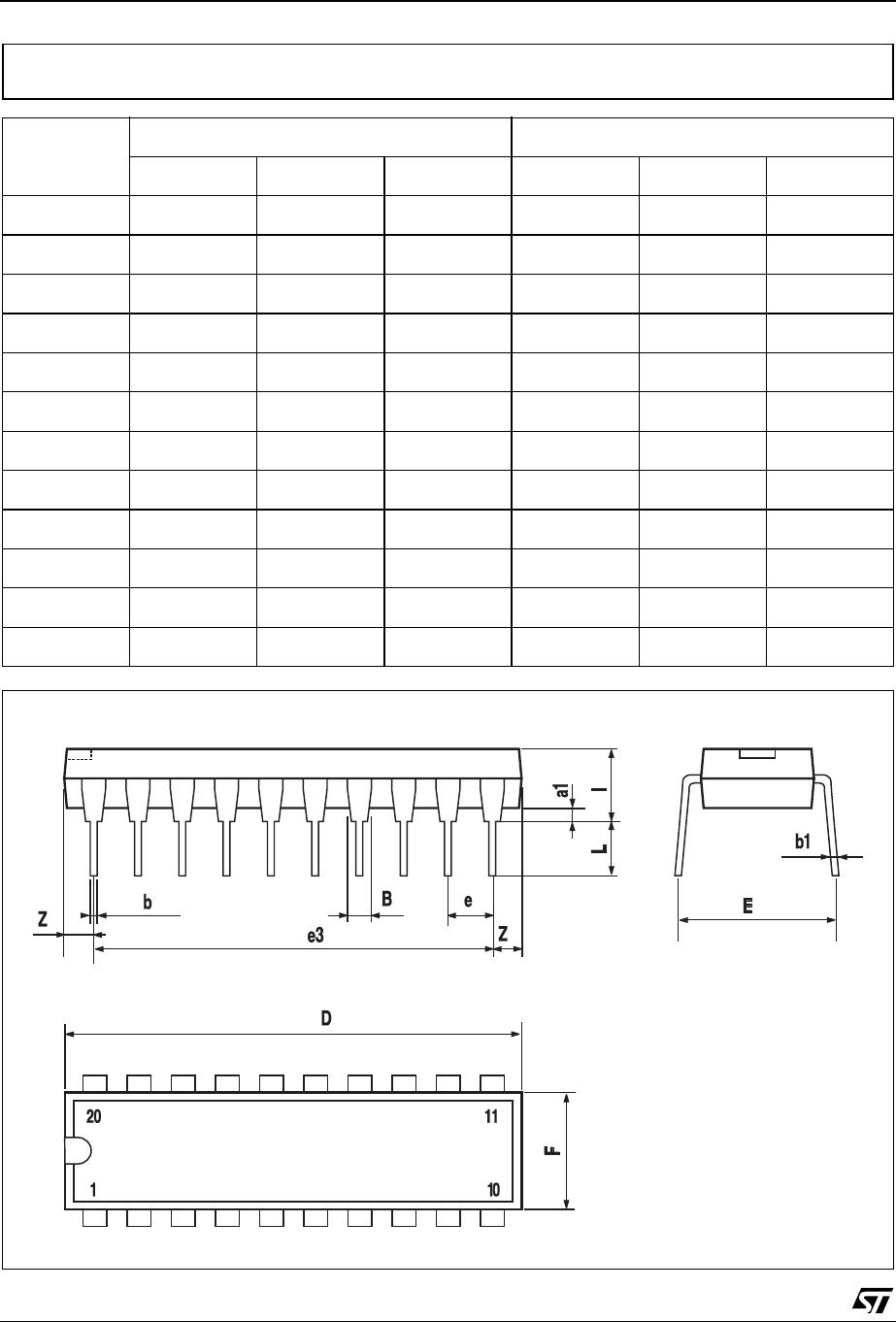
DIM.
mm.
inch
MIN.
TYP
MAX.
MIN.
TYP.
MAX.
a1
0.254
0.010
B
1.39
1.65
0.055
0.065
b
0.45
0.018
b1
0.25
0.0
10
D
25.4
1.000
E
8.5
0.335
e
2.54
0.100
e3
22.86
0.900
F
7.1
0.280
I
3.93
0.155
L
3.3
0.130
Z
1.34
0.053
Plastic DIP-20
(0.25) MECHANICAL DA
T
A
P001J
P1-P3
P4-P6
P7-P9
M74HCT540RM13TR
Mfr. #:
Buy M74HCT540RM13TR
Manufacturer:
STMicroelectronics
Description:
Buffers & Line Drivers Octal Bus Buffer
Lifecycle:
New from this manufacturer.
Delivery:
DHL
FedEx
Ups
TNT
EMS
Payment:
T/T
Paypal
Visa
MoneyGram
Western
Union
Products related to this Datasheet
M74HCT540B1R
M74HCT540RM13TR