Features
■ Thick fi lm technology
■ Power rating of 2 watts at 70 °C
■ Low resistance value available
■ RoHS compliant*
Applications
■ Current sensing
■ Power supplies
■ Stepper motor drives
■ Snubber resistor for fl yback power supplies
CRM2512 - High Power Current Sense Chip Resistors
*RoHS Directive 2002/95/EC Jan. 27, 2003 including annex and RoHS Recast 2011/65/EU June 8, 2011.
Specifi cations are subject to change without notice.
Users should verify actual device performance in their specifi c applications.
The device characteristics and parameters in this data sheet can and do vary in different applications and actual device performance may vary over time.
General Information
The Bourns
®
CRM2512 Series is a
thick fi lm power resistor with a rating of
2 watts in a standard 2512 chip format.
This product has a very wide resistance
range making it suitable for different
applications in power supply circuits
including current sensing and current
limiting.
DIMENSIONS:
MM
(INCHES)
Electrical Characteristics
Product Dimensions
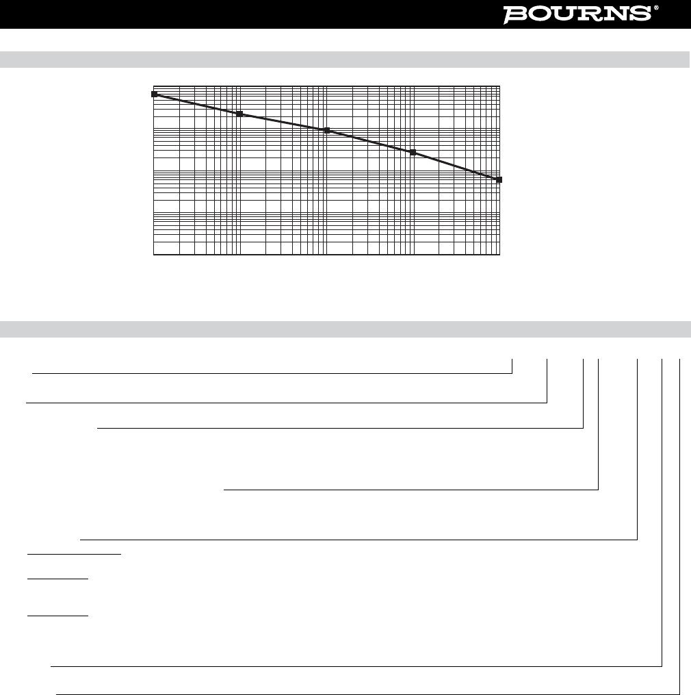
Derating Curve
Characteristic Data
Test ΔR Max.
Load Life (1000 hours)
1 % Tolerance < 1 %
5 % Tolerance < 3 %
Short Term Overload
1 % Tolerance < 1 %
5 % Tolerance < 2 %
Thermal Shock
1 % Tolerance < 0.5 %
5 % Tolerance < 1 %
6.3 ± 0.20
(0.248 ± 0.008)
TOP SIDE
3.1 ± 0.20
(0.122 ± 0.008)
0.6 ± 0.20
(0.024 ± 0.008)
0.6 ± 0.20
(0.024 ± 0.008)
1.8 ± 0.20
(0.070 ± 0.008)
Ambient Temperature (°C)
70 155
100
-55
Power Ratio (%)
Recommended Solder Pad Layout
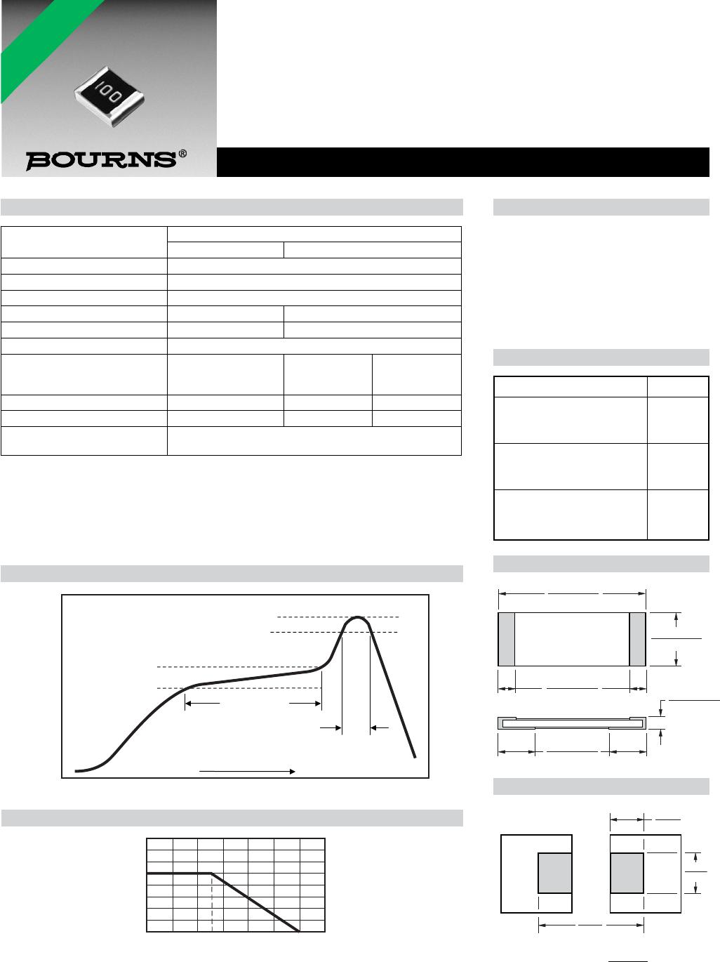
Soldering Profi le
50
100
150
200
250
Temperature (°C)
90 ± 30 seconds
Pre-heating Zone
150 °C
230 °C or higher
Peak 260 +5/-0 °C
180 °C
30 ± 10 seconds
Heating Time
Soldering Zone
For Standard Values Used in Capacitors, Inductors, and Resistors, click here.
Notes:
(1) CRM2512 2 W loading with total solder pad and trace size of 300 mm
2
.
(2) E = (PxR)
1/2
E: Working Voltage (V); P: Rated Power (W); R: Resistance Value (Ω)
(3) Jumper (0 Ω): Rated current 6 A maximum with 300 mm
2
pad. Temperature coeffi cient is not
applicable.
Characteristic
Model CRM2512
(0.047 to 0.91 Ω) (0 Ω,1 Ω to 1 M Ω)
Power Rating @ 70 °C 2 W
Operating Temp. Range -55 °C to +155 °C
Derated to Zero Load at +155 °C
Maximum Working Voltage 1349 mV 300 V
Maximum Overload Voltage 2698 mV 600 V
Insulation Resistance > 1000 MΩ
Resistance Range
0.047 - 0.91 Ω
(E24 Values)
0
Ω,
1.0 - 1 MΩ
(E24 Values)
1 Ω - 1 MΩ
(E96 + E24
Values)
Resistance Tolerance ±1 % & ±5 % ±5 % ±1 %
Temperature Coeffi cient ±100 PPM/°C ±200 PPM/°C ±100 PPM/°C
Zero Ohm Jumper
<0.02 Ω Max. Rated Current
6A
7.6
(.299)
3.7
(.146)
2.45
(.096)