74CBTLV3245QG8

INDUSTRIAL TEMPERATURE RANGE
IDT74CBTLV3245
LOW-VOLTAGE OCTAL BUS SWITCH
1
DECEMBER 2014INDUSTRIAL TEMPERATURE RANGE
The IDT logo is a registered trademark of Integrated Device Technology, Inc.
© 2015 Integrated Device Technology, Inc. DSC-5170/5
FUNCTIONAL BLOCK DIAGRAM
FEATURES:
Pin-out compatible with standard '245 Logic products
•5
ΩΩ
ΩΩ
Ω A/B bi-directional switch
Isolation under power-off conditions
Over-voltage tolerant
Latch-up performance exceeds 100mA
•V
CC = 2.3V - 3.6V, Normal Range
ESD > 2000V per MIL-STD-883, Method 3015;
> 200V using machine model (C = 200pF, R = 0)
Available in QSOP and TSSOP packages
APPLICATIONS:
3.3V High Speed Bus Switching and Bus Isolation
SIMPLIFIED SCHEMATIC, EACH SWITCH
IDT74CBTLV3245
LOW-VOLTAGE OCTAL
BUS SWITCH
DESCRIPTION:
The octal bus switch has standard 245 pinouts. The CBTLV3245 is
designed for asynchronous communication between data buses. When
Output Enable (OE) is low, the 8-bit bus switch is on and port A is connected
to Port B. When OE is high, the switch is off and a high impedance exists
between Port A and Port B.
To ensure the high-impedance state during power up or power down,
OE should be tied to VCC through a pullup resistor.
OE
AB
2
9
19
A1
A8
OE
B8
B1
18
11
SW
SW
INDUSTRIAL TEMPERATURE RANGE
2
IDT74CBTLV3245
LOW-VOLTAGE OCTAL BUS SWITCH
PIN CONFIGURATION
QSOP / TSSOP
TOP VIEW
Symbol Parameter Test Conditions Min. Max. Unit
VCC Supply Voltage 2.3 3.6 V
V
IH High-Level Control Input Voltage VCC = 2.3V to 2.7V 1.7 V
VCC = 2.7V to 3.6V 2
VIL Low-Level Control Input Voltage VCC = 2.3V to 2.7V 0.7 V
VCC = 2.7V to 3.6V 0.8
T
A Operating Free-Air Temperature 40 85 ° C
OPERATING CHARACTERISTICS, TA = 25°C
(1)
NOTE:
1. All unused control inputs of the device must be held at VCC or GND to ensure proper device operation.
Symbol Description Max Unit
VCC SupplyVoltage Range –0.5 to +4.6 V
VI Input Voltage Range –0.5 to +4.6 V
Continuous Channel Current 128 mA
IIK Input Clamp Current, VI/O < 0 50 mA
T
STG Storage Temperature –65 to +150 °C
ABSOLUTE MAXIMUM RATINGS
(1)
NOTE:
1. Stresses greater than those listed under ABSOLUTE MAXIMUM RATINGS may cause
permanent damage to the device. This is a stress rating only and functional operation
of the device at these or any other conditions above those indicated in the operational
sections of this specification is not implied. Exposure to absolute maximum rating
conditions for extended periods may affect reliability.
NOTE:
1. H = HIGH Voltage Level
L = LOW Voltage Level
Input
OE Operation
L A Port = B Port
H Isolation
FUNCTION TABLE
(1)
Pin Names Description
OE Output Enable (Active LOW)
A x Port A Inputs or Outputs
B x Port B Inputs or Outputs
PIN DESCRIPTION
VCC
OE
B
1
B2
B3
B4
B5
B6
B7
B8
A1
A2
A3
A4
A6
A7
A8
GND
2
3
4
5
6
7
8
9
10
11
12
13
14
15
16
17
18
19
20
1
NC
A5
INDUSTRIAL TEMPERATURE RANGE
IDT74CBTLV3245
LOW-VOLTAGE OCTAL BUS SWITCH
3
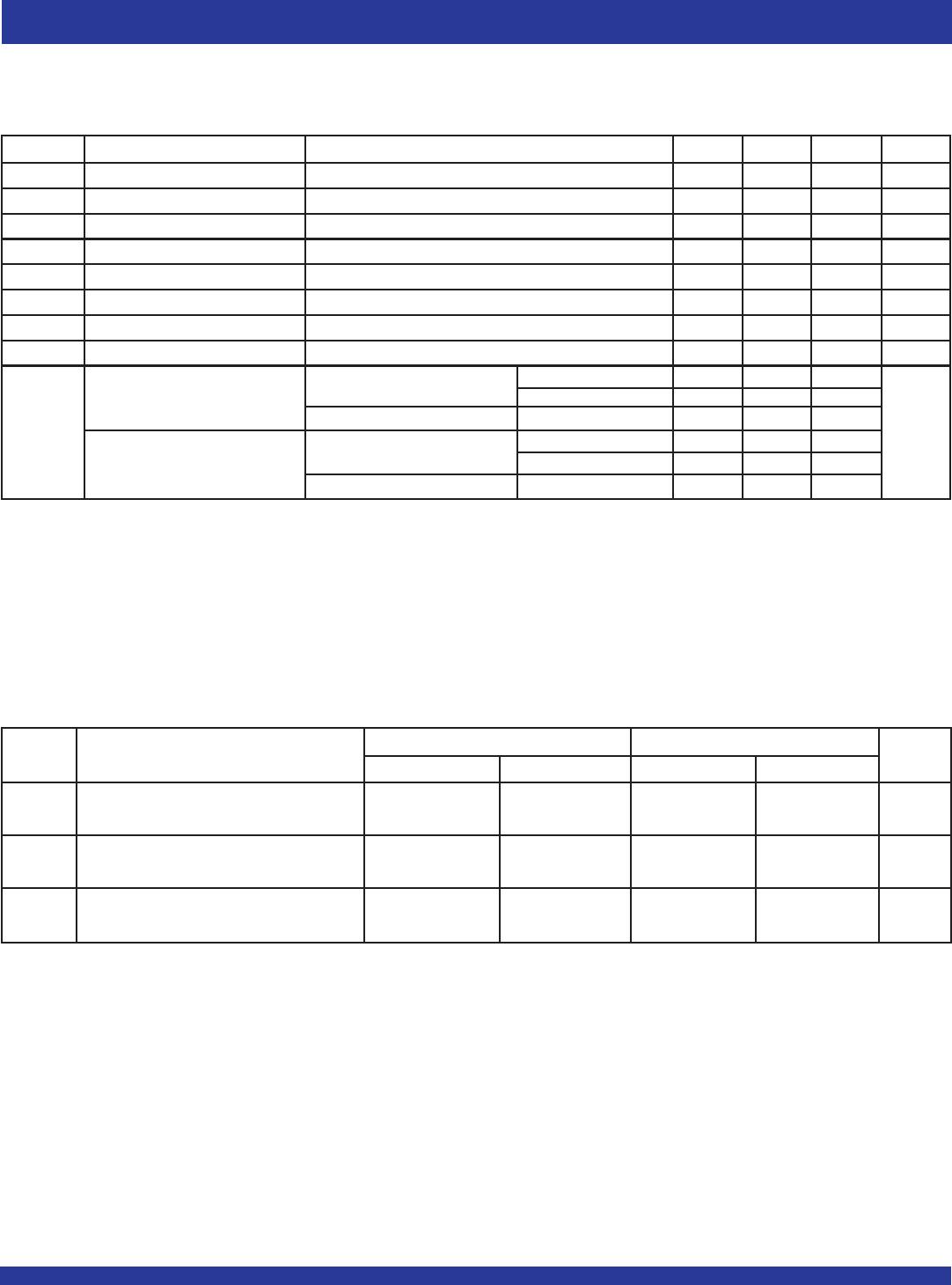
Symbol Parameter Test Conditions Min. Typ.
(1)
Max. Unit
VIK Control Inputs, Data Inputs VCC = 3V, II = –18mA –1.2 V
II Control Inputs VCC = 3.6V, VI = VCC or GND ±1 μA
IOZ Data I/O VCC = 3.6V, VO = 0 or 3.6V, switch disabled 5 μA
IOFF VCC = 0, VI or VO = 0 to 3.6V 50 μA
ICC VCC = 3.6V, IO = 0, VI = VCC or GND 10 μA
ΔICC
(2)
Control Inputs VCC = 3.6V, one input at 3V, other inputs at VCC or GND 300 μA
CI Control Inputs VI = 3V or 0 4 pF
CIO(OFF) VO = 3V or 0, OE = VCC —6 —pF
V
CC = 2.3V VI = 0 IO = 64mA 5 8
Typ. at VCC = 2.5V IO = 24mA 5 8
R
ON
(3)
VI = 1.7V IO = 15mA 27 40 Ω
V
I = 0 IO = 64mA 5 7
VCC = 3V IO = 24mA 5 7
VI = 2.4V IO = 15mA 10 15
DC ELECTRICAL CHARACTERISTICS OVER OPERATING RANGE
Following Conditions Apply Unless Otherwise Specified:
Operating Conditions: TA = –40°C to +85°C
VCC = 2.5V ± 0.2V VCC = 3.3V ± 0.3V
Symbol Parameter Min. Max. Min. Max. Unit
t
PD
(1)
Propagation Delay 0.15 0.25 ns
A to B or B to A
tEN Output Enable Time 1 4.5 1 4.2 ns
OE to A or B
tDIS Output Disable Time 1 5 1 5 ns
OE to A or B
NOTE:
1. The propagation delay is the calculated RC time constant of the typical on-state resistance of the switch and the specified load capacitance driven by an ideal voltage source
(zero output impedance).
SWITCHING CHARACTERISTICS
NOTES:
1. Typical values are at VCC = 3.3V, +25°C ambient.
2. The increase in supply current is attributable to each current that is at the specified voltage level rather than VCC or GND.
3. This is measured by the voltage drop between the A and B terminals at the indicated current through the switch.

74CBTLV3245QG8

Mfr. #:
Manufacturer:
IDT
Description:
Digital Bus Switch ICs OCTAL FET BUS SWITCH
Lifecycle:
New from this manufacturer.
Delivery:
DHL FedEx Ups TNT EMS
Payment:
T/T Paypal Visa MoneyGram Western Union