CR0603-FX-3571ELF

Features
n RoHS compliant*
n Power rating at 70 °C: CR0603 - 0.10 W,
CR0805 - 0.125 W, CR1206 - 0.25 W
n Tight tolerances of bottom electrode
width
n Suitable for all types of soldering processes
n Three layer contacting process with
nickel barrier prevents leaching and
provides excellent solderability
n Paper tape on reel for automatic
placement
CR0603/CR0805/CR1206 - Chip Resistors
*RoHS Directive 2002/95/EC Jan. 27, 2003 including
annex and RoHS Recast 2011/65/EU June 8, 2011.
Specifications are subject to change without notice.
The device characteristics and parameters in this data
sheet can and do vary in different applications and
actual device performance may vary over time.
Users should verify actual device performance in their
specific applications.
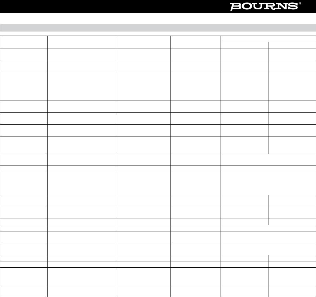
Electrical Characteristics
DIMENSIONS:
MM
(INCHES)
*RoHS COMPLIANT
LEAD FREE
*RoHS COMPLIANT
VERSIONS
AVAILABLE
LEAD FREE
VERSIONS ARE
RoHS COMPLIANT*
Characteristic Model CR0603 Model CR0805 Model CR1206
Power Rating @ 70 °C 1/10 W 1/8 W 1/4 W
Operating Temperature Range -55 °C to +155 °C
Derated to 0 Load at +155 °C
Maximum Working Voltage 50 V 150 V 200 V
Maximum Overload Voltage 100 V 300 V 400 V
10ohms≤R≤1Mohms
±100 PPM/°C
Resistance Range: 1 %
E-96 + E-24
1Mohms<R≤10Mohms
±200 PPM/°C
10ohms≤R≤10Mohms
±200 PPM/°C
Resistance Range: 5 %
E-24
1ohm≤R<10ohms
10Mohms<R≤20Mohms
±400 PPM/°C
Zero Ohm Jumper <0.05 ohm
Rated / Maximum Current
1 A / 2.5 A 2 A / 5 A 2 A / 5 A
AEC-Q200: Contact Bourns to conrm availiability.
For Standard Values Used in Capacitors, Inductors, and Resistors, click here.
Chip Dimensions
Model Model Model
Dimension CR0603 CR0805 CR1206
L
1.60±0.10 2.00±0.15 3.20±0.25
(0.063±0.004) (0.079±0.006) (0.126±0.010)
W
0.80±0.10 1.25±0.15 1.60±0.15
(0.031±0.004) (0.049±0.006) (0.063±0.006)
H
0.45±0.10 0.50±0.10 0.60±0.15
(0.018±0.004) (0.020±0.004) (0.024±0.006)
I1
0.30±0.20 0.40±0.20 0.50±0.25
(0.012±0.008) (0.016±0.008) (0.020±0.010)
I2
0.30±0.20 0.40±0.20 0.50±0.20
(0.012±0.008) (0.016±0.008) (0.020±0.010)
Derating Curve
Characteristic Data
Dimensional Drawings
L
H
I
2
I
2
W
I
1
I
1
100
80
60
40
20
0
Rated Power (%)
Ambient Temperature (°C)
-55
070
155
Overcoat
Resistor (Ru02)
(Jumper chip is
a conductor)
Alumina Substrate
Internal Electrode (Ag)
Secondary Electrode (Nickel Plated)
External Electrode
(tin-plated)
01R
CR0603/CR0805/CR1206 - Chip Resistors
Performance Characteristics
Specifications are subject to change without notice.
The device characteristics and parameters in this data sheet can and do vary in different applications and actual device performance may vary over time.
Users should verify actual device performance in their specific applications.
Test Procedure Method Specication
Test Limits DR
1 % 5 %
DC Resistance --
MIL-STD-202 303
EIA RS-396 4.4
MIL-R-55342D 4.7.2 ≤±1 % ≤±5.0 %
Low Temperature
Operation
-55 °C, 1 hour “OFF”;
45 minutes "ON"
MIL-R-55342D 4.7.4
EIA RS-396 4.6
MIL-R-55342D 4.7.4 ≤±(0.5 % + 0.05 Ω) ≤±(1.0 % + 0.05 Ω)
Short time
Overload
Rated Voltage x 2.5,
5 seconds:
CR0603: 100 V max.
CR0805: 300 V max.
CR1206: 400 V max.
MIL-R-55342D 4.7.5
EIA RS-396 4.7
MIL-R-55342D 4.7.5 ≤±(1 % + 0.05 Ω) ≤±(2 % + 0.05 Ω)
High Temperature
Exposure
+125 °C, 1000 hours
MIL-R-55342D 4.7.6
EIA RS-396 4.8
MIL-R-55342D 4.7.6 ≤±(1.0 % + 0.05 Ω) ≤+(2.0 % + 0.1 Ω)
Resistance to
Solder Heat
260 °C, 10 seconds MIL-R-55342D 4.7.7 MIL-R-55342D 4.7.7 ≤±(0.5 % + 0.05 Ω) ≤±(1.0 % + 0.05 Ω)
Moisture Resis-
tance
90-98 % RH, 10 cycles
MIL-STD-202 106D
EIA RS-396 4.9
MIL-R-55342D 4.7.8 ≤±(0.5 % + 0.05 Ω) ≤±(2.0 % + 0.05 Ω)
Load Life
+70 °C; 1.5 hours “ON”,
0.5 hours “OFF”; 1000 hours
MIL-STD-202 108
Condition D
EIA RS-396 4.12
MIL-R-55342D 4.7.10 ≤±(1.0 % + 0.05 Ω) ≤±(3.0 % + 0.1Ω)
Solderability +235 °C; 3 seconds
MIL-STD-202 208
EIA RS-396 4.11
MIL-R-55342D 4.7.11 ≥95 % of area covered
Terminal Strength Pull Test MIL-R-55342D 4.7.12 MIL-R-55342D 4.7.12 ≥500 g
Current Noise Quan-Tech Model 315B MIL-STD-202 308 MIL-R-55342D 6.6
R≤1 kW; 1 mV/V max.
R≤10 kW; 3 mV/V max.
R≤100 kW; 6 mV/V max.
R≤1 MW; 10 mV/V max.
Humidity, Steady
State
+40 °C; 90-95 % RH,
1344 hours
MIL-STD-202 103B
Condition D
-- ≤±(2.5 % + 0.05 Ω) ≤±(2.5 % + 0.05 Ω
Salt Spray 96 hours
MIL-STD-202 101D
Condition A
-- ≤±(1.0 % + 0.2 Ω) ≤±(1.0 % + 0.1 Ω
Vibration 10-2000 Hz, 6 hours MIL-STD-202 201A -- ≤±(0.5 % + 0.1 Ω) ≤±(1.0 % + 0.1 Ω
Voltage Coefcient -- MIL-STD-202 309 -- ≤100 ppm/V
Insulation Resis-
tance
Test potential: 500V
CR0603: 100 V
MIL-STD-202 302
Condition B
-- ≥1 GΩ
Dielectric With-
standing Voltage
-- MIL-STD-202 301 --
CR0805, CR1206: ≥500 V
CR0603: ≥300 V
Drop Test 1 m MIL-STD-202 203B -- ≤±(0.5 % + 0.1 Ω) ≤±(1 % + 0.1 Ω
Bending Test 5 mm/90 mm, 10 seconds -- -- ≤±(1 % + 0.05 Ω) ≤±(1 % + 0.05 Ω)
Thermal Shock
-55 °C for 30 minutes,
+155 °C for 30 minutes,
5 cycles
IEC 60115-1-4.19 -- ≤±(0.5% + 0.05 Ω) ≤±(1 % + 0.05 Ω)
Resistance to Dry
Heat
125 ±5 °C for 96 ±4 hours IEC 60115-1-4.23.2 -- ≤±(1 % + 0.05 Ω) ≤±(2 % + 0.1 Ω)
CR0603/CR0805/CR1206 - Chip Resistors
Soldering Prole for RoHS Compliant Chip Resistors and Arrays
25
75
125
175
225
275
050 100 150 200 250 300
Time (seconds)
Temperature (°C)
60 - 120 seconds
60 - 90
seconds
260 °C peak
190 °C
150 °C
220 °C
Ramp Down
6 °C/second
255 °C
Maximum of 20 seconds between
+255 °C and +260 °C
Ramp Up
3 °C/second maximum
10 seconds minimum
<1>
<1>
Packaging Dimensions (Conforms to EIA RS-481A)
1.5 +0.1/-0
(.056 + .004/-0)
Maximum 1 mm (.040) thick
*Cumulative tolerance over 10 holes: ±0.2 mm
1.75 ± 0.1
(.059 ± .004)
B
4.0 ± 0.1
(.157 ± .004)
2.0 ± 0.05
(.079 ± .002)
A
8.0 ± 0.2
(.315 ± .008)
3.5 ± 0.05
(.138 ± .002)
4.0 ± 0.1
(.157 ± .004)
20.5
(.807)
13.0 ± 0.5
(.512 ± .020)
2.0
(.080)
1.0 ± 0.2
(.040 ± .020)
10.0 ± 1.5
(.394 ± .059)
80.0 ± 1.0
(3.150 ± .040)
178.0 ± 2.0
(7.008 ± .080)
DIMENSIONS:
MM
(INCHES)
Series A B
CR0603 1.9 ± 0.2 1.1 ± 0.2
(.075 ± .008) (.043 ± .008)
CR0805 2.4 ± 0.2 1.65 ± 0.2
(.094 ± .008) (.065 ± .008)
CR1206 3.57 ± 0.2 2.00 ± 0.2
(.161 ± .008) (.079 ± .008)
Marking on reel: Part number, quantity, resistance value and tolerance, date code.
Specifications are subject to change without notice.
The device characteristics and parameters in this data sheet can and do vary in different applications and actual device performance may vary over time.
Users should verify actual device performance in their specific applications.

CR0603-FX-3571ELF

Mfr. #:
Manufacturer:
Bourns
Description:
Thick Film Resistors - SMD 3.57K ohm 1%
Lifecycle:
New from this manufacturer.
Delivery:
DHL FedEx Ups TNT EMS
Payment:
T/T Paypal Visa MoneyGram Western Union