B320B-13-F

B320B - B360B
Document number: DS30924 Rev. 10 - 2
1 of 5
www.diodes.com
April 2013
© Diodes Incorporated
B320B - B360B
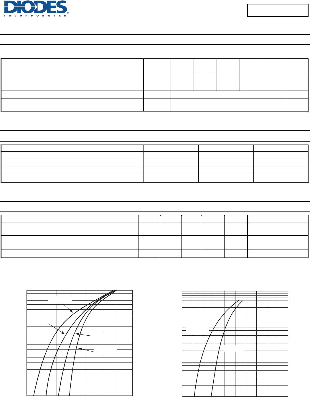
3.0A SURFACE MOUNT SCHOTTKY BARRIER RECTIFIER
Features
Guard Ring Die Construction for Transient Protection
Ideally Suited for Automated Assembly
Low Power Loss, High Efficiency
Surge Overload Rating to 125A Peak
For Use in Low Voltage, High Frequency Inverters, Free
Wheeling, and Polarity Protection Application
Totally Lead-Free & Fully RoHS Compliant (Notes 1 & 2)
Halogen and Antimony Free. “Green” Device (Note 3)
Qualified to AEC-Q101 Standards for High Reliability
PPAP Capable (Note 4)
Mechanical Data
Case: SMB
Case Material: Molded Plastic. "Green" Molding Compound. UL
Flammability Classification Rating 94V-0
Moisture Sensitivity: Level 1 per J-STD-020
Terminals: Lead Free Plating (Matte Tin Finish). Solderable per
MIL-STD-202, Method 208
Polarity: Cathode Band
Weight: 0.093 grams (approximate)
Ordering Information (Note 5)
Part Number* Compliance Case Packaging
B3xxB-13-F Standard SMB 3000/Tape & Reel
B340BQ-13-F Automotive SMB 3000/Tape & Reel
* xx = Device type, e.g. B320B-13-F (SMB package).
Notes: 1. No purposely added lead. Fully EU Directive 2002/95/EC (RoHS) & 2011/65/EU (RoHS 2) compliant.
2. See http://www.diodes.com/quality/lead_free.html for more information about Diodes Incorporated’s definitions of Halogen- and Antimony-free, "Green"
and Lead-free.
3. Halogen- and Antimony-free "Green” products are defined as those which contain <900ppm bromine, <900ppm chlorine (<1500ppm total Br + Cl) and
<1000ppm antimony compounds.
4. Automotive products are AEC-Q101 qualified and are PPAP capable. Automotive, AEC-Q101 and standard products are electrically and thermally the
same, except where specified. For more information, please refer to http://www.diodes.com/quality/product_compliance_definitions/.
5. For packaging details, go to our website at http”//www.diodes.com/products/packages.html.
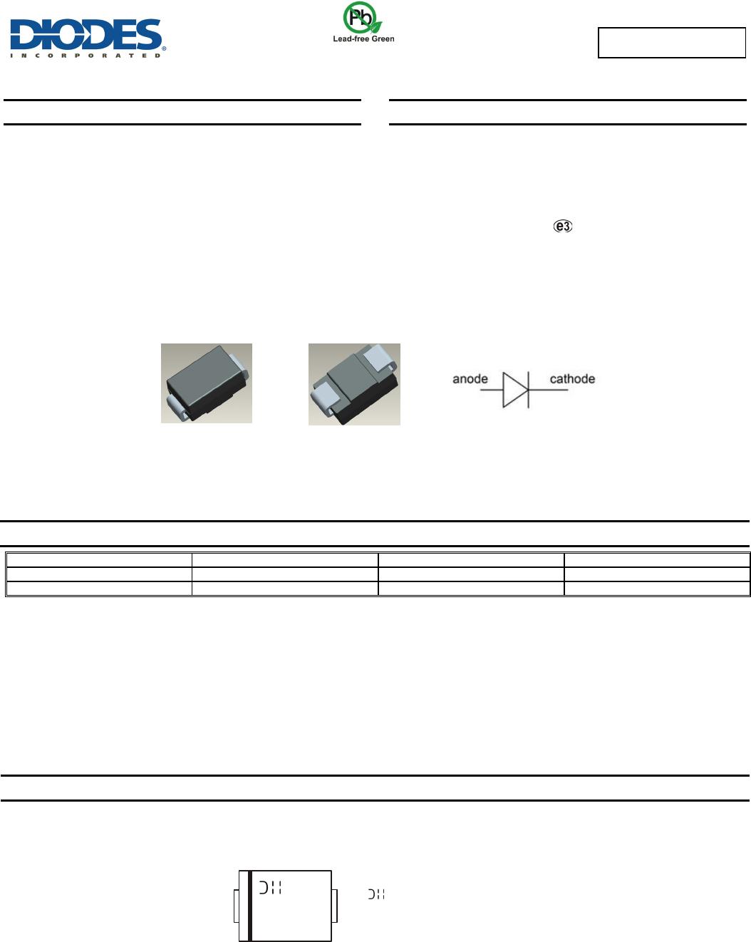
Marking Information
Top View Bottom View
Bxxx(x) = Product type marking code, ex: B320B
= Manufacturers’ code marking
YWW = Date code marking
Y = Last digit of year (ex: 3 for 2013)
WW = Week code (01 to 53)
YWW
Bxxx(x)
B320B - B360B
Document number: DS30924 Rev. 10 - 2
2 of 5
www.diodes.com
April 2013
© Diodes Incorporated
B320B - B360B
Maximum Ratings (@T
A
= +25°C, unless otherwise specified.)
Single phase, half wave, 60Hz, resistive or inductive load.
For capacitance load, derate current by 20%.
Characteristic Symbol B320B B330B
B340B/
B340BQ
B350B B360B Unit
Peak Repetitive Reverse Voltage
Working Peak Reverse Voltage
DC Blocking Voltage
V
RRM
V
RWM
V
R
20 30 40 50 60 V
Average Rectified Output Current @ T
T
=+100°C I
O
3.0 A
Non-Repetitive Peak Forward Surge Current 8.3ms
single half sine-wave superimposed on rated load
I
FSM
100 A
Thermal Characteristics
Characteristic Symbol Value Unit
Typical Thermal Resistance, Junction to Terminal (Note 6)
R
θJT
25 °C/W
Typical Thermal Resistance, Junction to Ambient (Note 6)
R
θJA
95 °C/W
Operating Temperature Range
T
J
-55 to +150 °C
Storage Temperature Range
T
STG
-55 to +150 °C
Electrical Characteristics (@T
A
= +25°C, unless otherwise specified.)
Characteristic Symbol Min Typ Max Unit Test Condition
Forward Voltage Drop
B320B,B330B,B340B,B340BQ
B350B, B360B
V
F
0.50
0.70
V
I
F
= 3.0A, T
A
= +25°C
Leakage Current (Note 7)
I
R
0.5
20
mA
@ Rated V
R
, T
A
= +25°C
@ Rated V
R
, T
A
= +100°C
Total Capacitance
C
T
200 pF
V
R
= 4V, f = 1MHz
Notes: 6. Thermal Resistance: Junction to terminal, unit mounted on glass epoxy substrate with 2x3mm copper pad.
7. Short duration pulse test used to minimize self-heating effect.
0.1
1.0
10
0.1
0.3
0.40.2
0.5
0.6
0.7 0.8
I , INS
T
AN
T
ANE
O
U
S
F
O
R
WA
R
D
C
U
R
R
EN
T
(A)
F
V , INSTANTANEOUS FORWARD VOLTAGE (V)
Figure 1 Typical Forward Characteristics - B320B thru B340B
F
T = 25C
A
°
T = 75C
A
°
T = 125C
A
°
T = -25C
A
°
0.01
0.1
1.0
10
0 0.2 0.4 0.6
0.8 1.0
I , INS
T
AN
T
ANE
O
U
S
F
O
R
WA
R
D
C
U
R
R
EN
T
(A)
F
V , INSTANTANEOUS FORWARD VOLTAGE (V)
Figure 2 Typical Forward Characteristics - B350B thru B360B
F
T = 125ºC
A
T = 25ºC
A
B320B - B360B
Document number: DS30924 Rev. 10 - 2
3 of 5
www.diodes.com
April 2013
© Diodes Incorporated
B320B - B360B
100
10
1
0.1
0.01
1,000
10,000
020 4060
V , INSTANTANEOUS REVERSE VOLTAGE (V)
Figure 3 Typical Reverse Characteristics, B320B thru B340B
R
10 30 50
T = 25C
A
°
T = 125C
A
°
T = -25C
A
°
T= 75C
A
°
I , INSTANTANEOUS REVERSE CURRENT ( A)
R
100
10
1
0.1
1,000
10,000
0
20
40 60
70
V , INSTANTANEOUS REVERSE VOLTAGE (V)
Figure 4 Typical Reverse Characteristics, B350B thru B360B
R
10
30 50
T = 25C
A
°
T = 125 C
A
°
T = 70C
A
°
I , INSTANTANEOUS REVERSE CURRENT ( A)
R
10
100
1,000
0.1 1 10 100
C
,
T
O
T
AL
C
A
P
A
C
I
T
AN
C
E (p
F
)
T
V , DC REVERSE VOLTAGE (V)
Figure 5 Total Capacitance vs. Reverse Voltage
R
1
f = 1MHz
0
0.5
1.0
25 50 75 100 125 150
I AVE
R
A
G
E
F
O
R
WA
R
D
C
U
R
R
EN
T
(A)
F(AV),
T , TERMINAL TEMPERATURE ( C)
Figure 6 Forward Current Derating Curve
T
°
1.5
2.0
2.5
3.0
0
20
40
60
80
100
110100
I,
P
EAK
F
O
R
WA
R
D S
U
R
G
E
C
U
R
R
EN
T
(A)
FSM
NUMBER OF CYCLES AT 60 Hz
Figure 7 Max Non-Repetitive Peak Forward Surge Current
Single Half-Sine-Wave
T = 100°C
T

B320B-13-F

Mfr. #:
Manufacturer:
Diodes Incorporated
Description:
Schottky Diodes & Rectifiers 20V 3A
Lifecycle:
New from this manufacturer.
Delivery:
DHL FedEx Ups TNT EMS
Payment:
T/T Paypal Visa MoneyGram Western Union

Products related to this Datasheet