Design and specifications are each subject to change without notice. Ask factory for the current technical specifications before purchase and/or use.
Should a safety concern arise regarding this product, please be sure to contact us immediately.
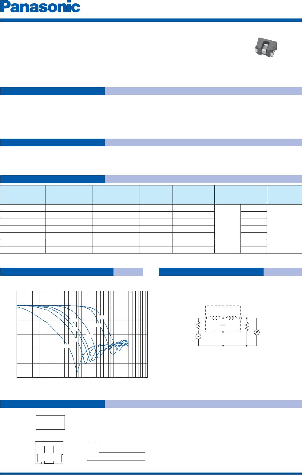
Coil type EMI Filters
The following are precautions for individual products. Please also refer to the common precautions for EMC Components
in this catalog.
1. Operation range and environments
1 These products are designed and manufactured for general and stan dard use in general elec tron ic
equipment (e.g. AV equipment, home electric ap pli anc es, office equipment, information and com mu ni ca tion
equipment)
2 These products are not intended for use in the following special conditions. Be fore using the products, care ful ly
check the effects on their quality and performance, and determine whether or not they can be used.
• In liquid, such as water, oil, chemicals, or organic solvent
• In direct sunlight, outdoors, or in dust
• In salty air or air with a high concentration of corrosive gas, such as Cl
2
, H
2
S, NH
3
, SO
2
, or NO
2
• In an environment where these products cause dew condensation
2. Handling
1 Do not bring magnets or magnetized materials close to the product. The influence of their magnetic field can
change the inductance value.
2 Do not apply strong mechanical shocks by either dropping or collision with other parts.
Excessive schock can damage the part.
3. Land pattern design
1 Please refer to the recommended land pattern for each type shown on the datasheet.
2 In case of reflow soldering, consider the layout because taller components close to EMI filters tend to block
thermal conduction.
4. Mounting
1 Avoid excessive placement force.
2 Do not bend or twist the PWB after mounting the part.
5. Cleaning
1 Do not use acid or alkali agents. Some cleaning solvents may damage the part.
Confirm by testing the reliability in advance of mass production.
2 If Ultrasonic cleaning is used, please confirm the reliability in advance.
It is possible that combined resonance of component, PWB and cavitation can cause an abnormal vibration
mode to exist causing damage.
Safety Precautions
Oct. 201403