ADXL345TCCZ-EP-RL7

Enhanced Product ADXL345-EP
Rev. B | Page 7 of 12
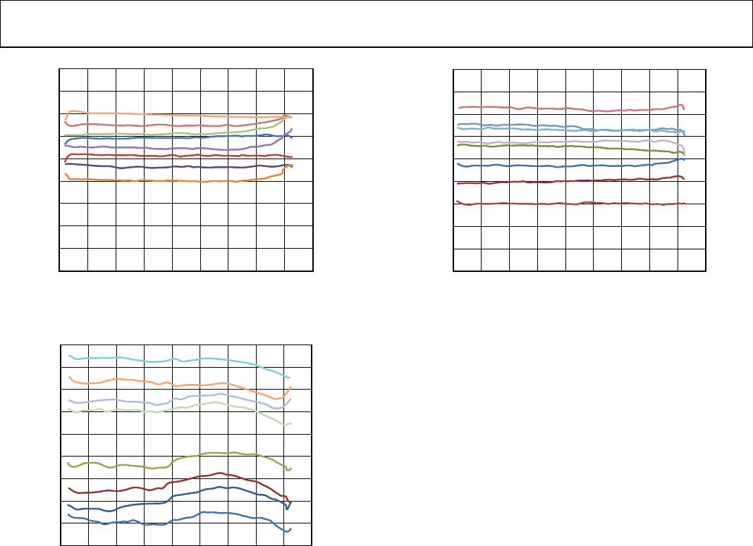
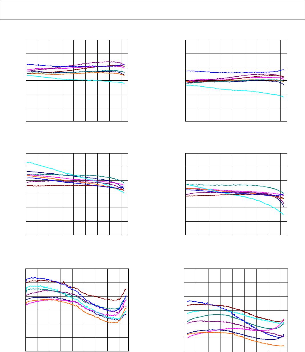
TYPICAL PERFORMANCE CHARACTERISTICS
150
100
50
0
–50
–100
–150
–60 –40 –20 0 20 40 60 80 100
TEMPERATURE (°C)
OUTPUT (mg)
10413-004
Figure 3. X-Axis Zero g Offset vs. Temperature
Eight Parts in Sockets, V
S
= 3.6 V
150
100
50
0
–50
–100
–150
–60 –40 –20 0 20 40 60 80 100
TEMPERATURE (°C)
OUTPUT (mg)
10413-005
Figure 4. Y-Axis Zero g Offset vs. Temperature
Eight Parts in Sockets, V
S
= V
DD I/O
= 3.6 V
250
200
150
100
50
0
–50
–60 –40 –20 0 20 40 60 80 100
TEMPERATURE (°C)
OUTPUT (mg)
10413-011
Figure 5. Z-Axis Zero g Offset vs. Temperature
Eight Parts in Sockets, V
S
= V
DD I/O
= 3.6 V
150
100
50
0
–50
–100
–150
–60 –40 –20 0 20 40 60 80 100
TEMPERATURE (°C)
OUTPUT (mg)
10413-007
Figure 6. X-Axis Zero g Offset vs. Temperature
Eight Parts in Sockets, V
S
= 2.5 V
150
100
50
0
–50
–100
–150
–60 –40 –20 0 20 40 60 80 100
TEMPERATURE (°C)
OUTPUT (mg)
10413-008
Figure 7. Y-Axis Zero g Offset vs. Temperature
Eight Parts Soldered to PCB, V
S
= V
DD I/O
= 2.5 V
100
0
150
250
200
50
–50
–60 –40 –20 0 20 40 60 80 100
TEMPERATURE (°C)
OUTPUT (mg)
10413-012
Figure 8. Z-Axis Zero g Offset vs. Temperature
Eight Parts Soldered to PCB, V
S
= V
DD I/O
= 2.5 V
ADXL345-EP Enhanced Product
Rev. B | Page 8 of 12
256
258
260
254
252
248
246
244
242
250
–60 –40 –20 0 20 40 60 80 100 120
TEMPERATURE (°C)
SENSITIVITY (LSB/g)
10413-006
Figure 9. X-Axis Sensitivity vs. Temperature
Eight Parts in Sockets, V
S
= V
DD I/O
= 2.5 V
258
260
256
254
252
250
248
246
244
242
–60 –40 –20 0 20 40 60 80 100 120
TEMPERATURE (°C)
SENSITIVITY (LSB/g)
10413-010
Figure 10. Z-Axis Sensitivity vs. Temperature
Eight Parts in Sockets, V
S
= V
DD I/O
= 2.5 V
258
260
256
254
252
248
246
244
242
250
–60 –40 –20 0 20 40 60 80 100 120
TEMPERATURE (°C)
SENSITIVITY (LSB/g)
10413-009
Figure 11. Y-Axis Sensitivity vs. Temperature
Eight Parts in Sockets, V
S
= V
DD I/O
= 2.5 V
Enhanced Product ADXL345-EP
Rev. B | Page 9 of 12
OUTLINE DIMENSIONS
BOTTOM VIEW
TOP VIEW
END VI
EW
SEATING
PLANE
1.00
0.95
0.85
5.00
BSC
3.00
BSC
PAD A1
CORNER
0.79
0.74
0.69
1
6
7
8
14
13
0.80
BSC
1.01
1.50
0.49
0.50
0.49
0.813 × 0.50
03-16-2010-A
Figure 12. 14-Terminal Land Grid Array [LGA]
(CC-14-1)
Solder Terminations Finish Is Au over Ni
Dimensions shown in millimeters
ORDERING GUIDE
Model
1
Measurement
Range (g)
Specified
Voltage (V)
Temperature
Range Package Description
Package
Option
ADXL345TCCZ-EP ±2, ±4, ±8, ±16 2.5 55°C to +105°C 14-Terminal Land Grid Array [LGA] CC-14-1
ADXL345TCCZ-EP-RL7 ±2, ±4, ±8, ±16 2.5 55°C to +105°C 14-Terminal Land Grid Array [LGA] CC-14-1
ADXL345TCCZ-EP-RL ±2, ±4, ±8, ±16 2.5 55°C to +105°C 14-Terminal Land Grid Array [LGA] CC-14-1
1
Z = RoHS Compliant Part.

ADXL345TCCZ-EP-RL7

Mfr. #:
Manufacturer:
Analog Devices Inc.
Description:
Accelerometers 3-Axis Low g Digital-Output
Lifecycle:
New from this manufacturer.
Delivery:
DHL FedEx Ups TNT EMS
Payment:
T/T Paypal Visa MoneyGram Western Union

Products related to this Datasheet