Design and specifications are each subject to change without notice. Ask factory for the current technical specifications before purchase and/or use.
Should a safety concern arise regarding this product, please be sure to contact us immediately.
Plastic Film Capacitors
●
Rated voltage : 630 V.DC, Capacitance tolerance : ±3 %(H)
●
Rated voltage : 1250 V.DC, Capacitance tolerance : ±5 %(J)
●
Rated voltage : 3000 V.DC, Capacitance tolerance : ±5 %(J)
✽
( ) : Suffi x for lead form
✽
( ) : Suffi x for lead form
Part No.
Capacitance
(µF)
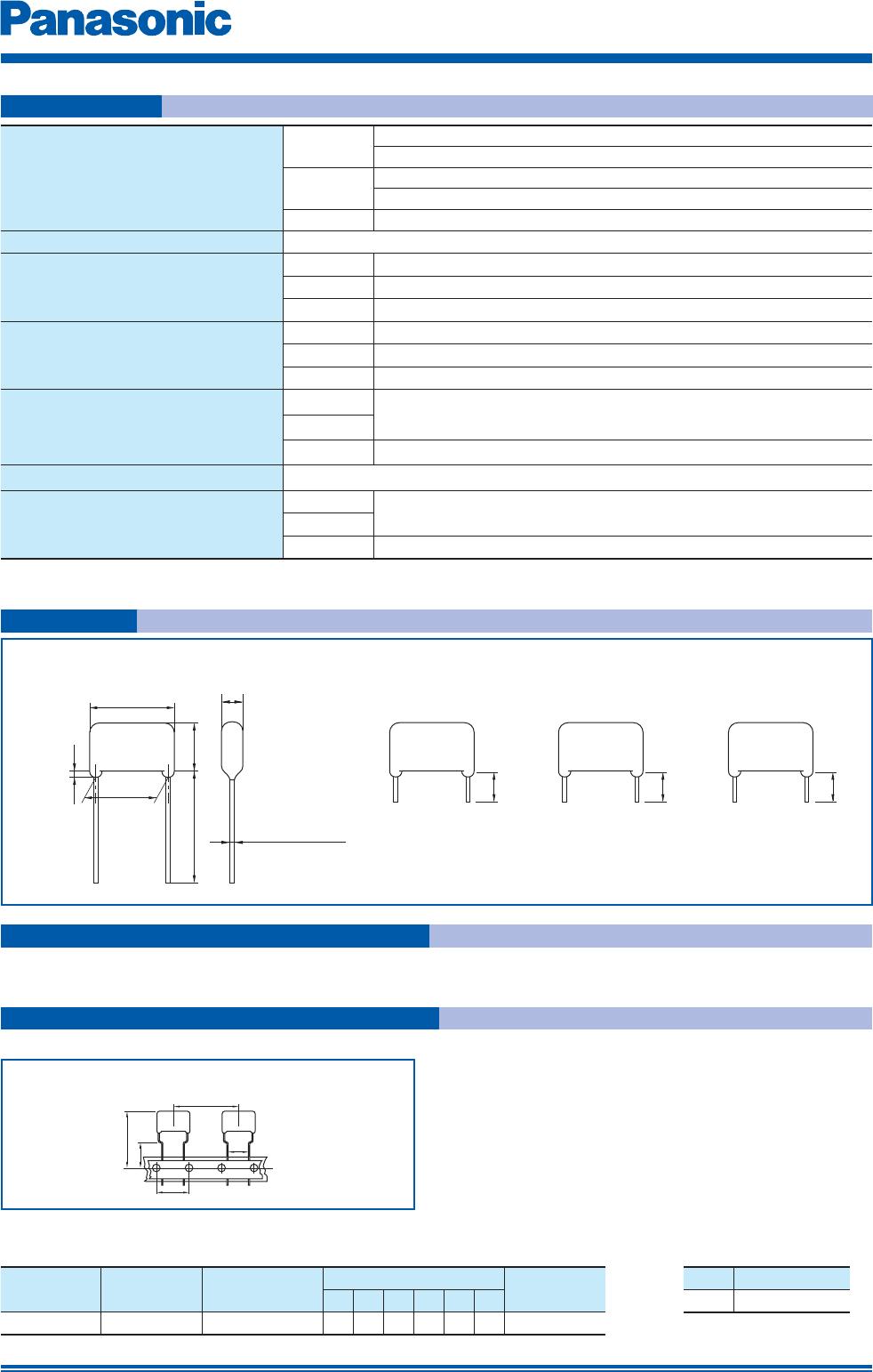
Dimensions (mm) Min. order Q'ty
L max. T max.
H max. F G max.
f
d
Taping
7.5 mm
Bulk
ECWH6104HC( ) 0.10 20.7 8.6 13.5 17.5 1.5 0.8 350
1000
ECWH6114HC( ) 0.11 20.7 9.0 13.9 17.5 1.5 0.8
300
ECWH6124HC( ) 0.12 20.7 9.4 14.3 17.5 1.5 0.8
ECWH6184HC( ) 0.18 20.7 11.5 16.3 17.5 1.5 0.8 250
ECWH6214HC( ) 0.21 20.7 12.4 17.2 17.5 1.5 0.8
200
ECWH6244HC( ) 0.24 20.7 13.2 18.1 17.5 1.5 0.8
700
ECWH6274HC( ) 0.27 20.7 14.0 18.9 17.5 1.5 0.8
ECWH6284HC( ) 0.28 20.7 14.3 19.1 17.5 1.5 0.8
ECWH6304HC( ) 0.30 20.7 14.8 19.6 17.5 1.5 0.8
ECWH6324HC( ) 0.32 20.7 14.5 20.9 17.5 1.5 0.8
ECWH6334HC( ) 0.33 20.7 14.7 21.1 17.5 1.5 0.8
Part No.
Capacitance
(µF)
Dimensions (mm) Min. order Q'ty
L max. T max.
H max. F G max.
f
d Bulk
ECWHC3B803JA 0.08 20.7 12.0 19.0 17.5 1.5 0.8
700
ECWHC3B104JA 0.10 20.7 13.5 20.6 17.5 1.5 0.8
ECWHC3B114JA 0.11 20.7 14.2 21.3 17.5 1.5 0.8
600
ECWHC3B124JA 0.12 20.7 14.9 21.9 17.5 1.5 0.8
Part No.
Capacitance
(µF)
Dimensions (mm) Min. order Q'ty
L max. T max.
H max. F G max.
f
d Bulk
ECWHC3F242J( ) 0.0024 25.8 6.1 10.9 22.5 1.5 0.8
1000
ECWHC3F362J( ) 0.0036 25.8 7.2 11.9 22.5 1.5 0.8
ECWHC3F392J( ) 0.0039 25.8 7.5 12.2 22.5 1.5 0.8
ECWHC3F432J( ) 0.0043 25.8 6.5 11.2 22.5 1.5 0.8
ECWHC3F562J( ) 0.0056 25.8 7.3 12.0 22.5 1.5 0.8
ECWHC3F822J( ) 0.0082 25.8 7.5 15.3 22.5 1.5 0.8
ECWHC3F103J( ) 0.01 25.8 8.2 16.1 22.5 1.5 0.8
Rating · Dimensions · Quantity
Feb. 201601