DC1901A

1
dc1901af
DEMO MANUAL DC1901A
DESCRIPTION
LTC3639EMSE
High Efficiency 150V, 100mA
Synchronous Buck Converter
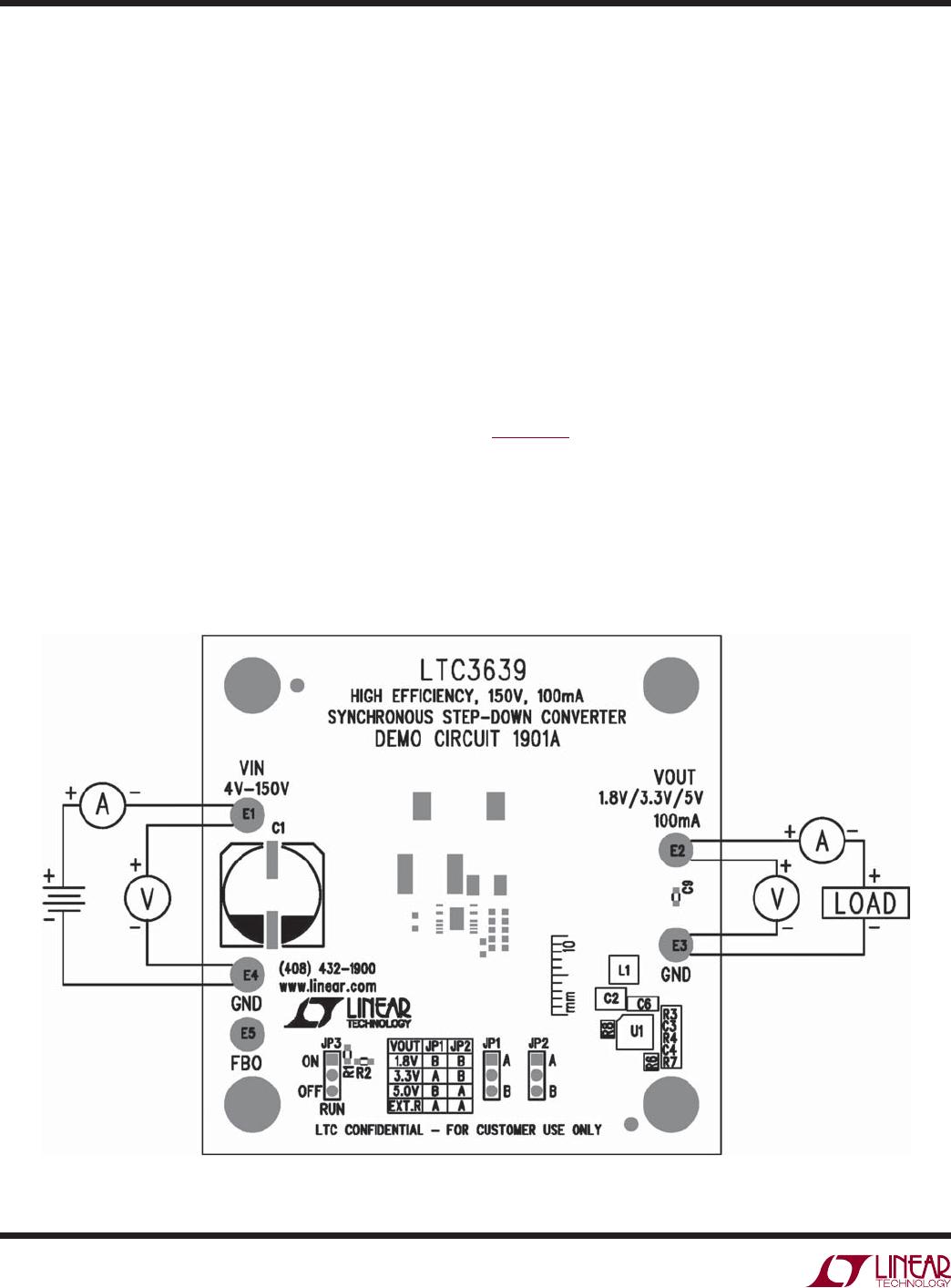
Demonstration circuit 1901A is a 150V input, 100mA
output DC/DC power supply featuring the LTC3639. The
IC operates in a high efficiency Burst Mode
®
operation
and includes internal high and low side power MOSFETs.
The board will accept an input voltage between 4V and
150V, and provide jumper selected output voltages of
1.8V, 3.3V, 5V and an option for additional voltages. The
IC includes internal soft-start and a provision for increas-
ing soft-start time.
Included on the board is an ON/OFF jumper that can also
be configured as a precision undervoltage lockout. Ad-
ditional PC pads are included for programming current
limit to optimize efficiency and for reducing output voltage
ripple and reducing component size. A terminal (FBO)
L, LT, LTC, LTM, Linear Technology, the Linear logo and Burst Mode are registered trademarks
of Linear Technology Corporation. All other trademarks are the property of their respective
owners.
PERFORMANCE SUMMARY
is included to allow multiple boards to be paralleled for
higher output current.
Output voltage between 800mV and V
IN
can be programmed
using optional resistors. (Higher voltage rating output
capacitors may be required.)
The LTC3639 data sheet gives a complete description of the
IC operation and application information. The data sheet
must be read in conjunction with this quick start guide.
Design files for this circuit board are available at
http://www.linear.com/demo
Specifications are at T
A
= 25°C
PARAMETER CONDITION VALUE
Input Voltage Range 4V to 150V
1.8V Output Voltage V
IN
= 12V, I
OUT
= 0A to 100mA 1.8V ±2%
3.3V Output Voltage V
IN
= 12V, I
OUT
= 0A to 100mA 3.3V ±2%
5V Output Voltage V
IN
= 12V, I
OUT
= 0A to 100mA 5V ±2%
Maximum Output Current, I
OUT
V
IN
= 4V to 150V, V
OUT
= 1.8V, 3.3V or 5V 100mA
Typical Efficiency V
IN
= 12V, V
OUT
= 5V, I
OUT
= 100mA 87.3%
Typical Output Ripple V
IN
= 150V, V
OUT
= 5V, I
OUT
= 100mA (20MHz BW) 66mV
P-P
2
dc1901af
DEMO MANUAL DC1901A
QUICK START PROCEDURE
Demonstration circuit 1901A is easy to set up to evaluate
the performance of the LTC3639. Refer to Figure 1 for
the proper measurement equipment setup and follow the
procedure below:
1. With power off, connect the input power supply (set
for 0V) to V
IN
and GND (input return).
2. Select 5V output using jumper JP1 (B position) and
JP2 (A position). Select ON position for JP3.
3. Connect the 5V output load between V
OUT
and GND
(Initial load: no load).
4. Connect the DVMs to the input and outputs.
5. Turn on the input power supply and slowly increase to
12V. Check for the proper output voltages. (5V output
should be within 5V ±2%.)
6. Once the proper output voltages are established, ad-
just the loads within the operating range and observe
the output voltage regulation, ripple voltage and other
parameters.
7. With power off, move jumpers JP1 and JP2 to the other
fixed voltage settings (1.8V or 3.3V). Repeat steps 5
and 6. Check for the proper output voltage and other
parameters.
NOTE: When measuring the output or input voltage ripple,
do not use the long ground lead on the oscilloscope probe.
See Figure 2 for the proper scope probe technique. Short,
stiff leads need to be soldered to the (+) and (–) terminals
of an output capacitor. The probe’s ground ring needs to
touch the (–) lead and the probe tip needs to touch the
(+) lead.
ADDITIONAL NOTES:
CAUTION:
Be careful when testing with high voltage. High
voltage can result in an electric shock if care is
not taken.
For 5V output, V
IN
input voltage should be at least 5V or
higher.
Figure 1. Proper Measurement Equipment Setup
3
dc1901af
DEMO MANUAL DC1901A
LTC3639 5V
OUT
LTC3639 3.3V
OUT
LTC3639 1.8V
OUT
Figure 3. Efficiency vs Load Current
Figure 2. Measuring Output Voltage Ripple
+–
V
OUT
GND
C
OUT
QUICK START PROCEDURE
LOAD CURRENT (A)
0
EFFICIENCY (%)
90
45
85
75
65
55
80
70
60
50
40
50 9030 70
dc1901 F03a
10040 8020 6010
12V
IN
, 5V
OUT
36V
IN
, 5V
OUT
120V
IN
, 5V
OUT
LOAD CURRENT (A)
0
EFFICIENCY (%)
90
45
85
75
65
55
80
70
60
50
40
50 9030 70
dc1901 F03b
10040 8020 6010
12V
IN
, 3.3V
OUT
36V
IN
, 3.3V
OUT
120V
IN
, 3.3V
OUT
LOAD CURRENT (A)
0
EFFICIENCY (%)
90
45
85
75
65
55
80
70
60
50
40
50 9030 70
dc1901 F03c
10040 8020 6010
12V
IN
, 1.8V
OUT
36V
IN
, 1.8V
OUT
120V
IN
, 1.8V
OUT

DC1901A

Mfr. #:
Manufacturer:
Analog Devices Inc.
Description:
Power Management IC Development Tools LTC3639EMSE Demo Board ? High Efficiency
Lifecycle:
New from this manufacturer.
Delivery:
DHL FedEx Ups TNT EMS
Payment:
T/T Paypal Visa MoneyGram Western Union

Products related to this Datasheet