AVAILABLE
Functional Diagrams
Pin Configurations appear at end of data sheet.
Functional Diagrams continued at end of data sheet.
UCSP is a trademark of Maxim Integrated Products, Inc.
For pricing, delivery, and
ordering information, please contact Maxim Direct
at 1-888-629-4642, or visit Maxim’s website at www.maximintegrated.com.
DESCRIPTION
The DS2715 is well suited for cost-sensitive charger
applications where the battery pack is either internal
or external to the application. It has been optimized for
safe and reliable charging of 1 to 10 NiMH cells in
series. The internal gain block can be selected as
either a comparator or transconductance amplifier for
charge current regulation. This makes the DS2715
configurable as a switched DC charger, a linear
current regulator, or a switchmode current source.
The DS2715 pre-conditions severely depleted cells
before entering full charge mode. It terminates full
charge using the dT/dt technique, which requires an
external sensing thermistor. Over-temperature, under-
temperature, and over-voltage detection prevents
charging under unsafe conditions. A user selectable
charge timer allows charge rates from 0.167C to 2C.
FAST-CHARGE, TOPOFF and DONE modes are
included for highly reliable, safe charging of NiMH
cells. Discharge mode allows the DS2715 to enter a
low power sleep state while the cell pack is being
discharged.
FEATURES
Charges 1 to 10 NiMH Cells
FAST-CHARGE at up to a 2C Rate
PRECHARGE and TOPOFF Charge Modes Help
Cell Conditioning
Load Detection Allows the DS2715 to Enter Low
Power Sleep Mode (Less than 10µA) while the
Cell Pack is Discharged
dT/dt Charge Termination Eliminates Cell Charge
Stress
Monitors Voltage, Temperature, and Time for
Safety and Secondary Termination
Regulates Current through Either Linear Control
or Switch-Mode Control
LED Output Displays Charge State
Small 16-Pin SO Package
APPLICATIONS
Portable DVD Players
Portable Television Sets
Handheld Gaming
Test Equipment
Handheld POS Terminals
PIN CONFIGURATION
Table 1.
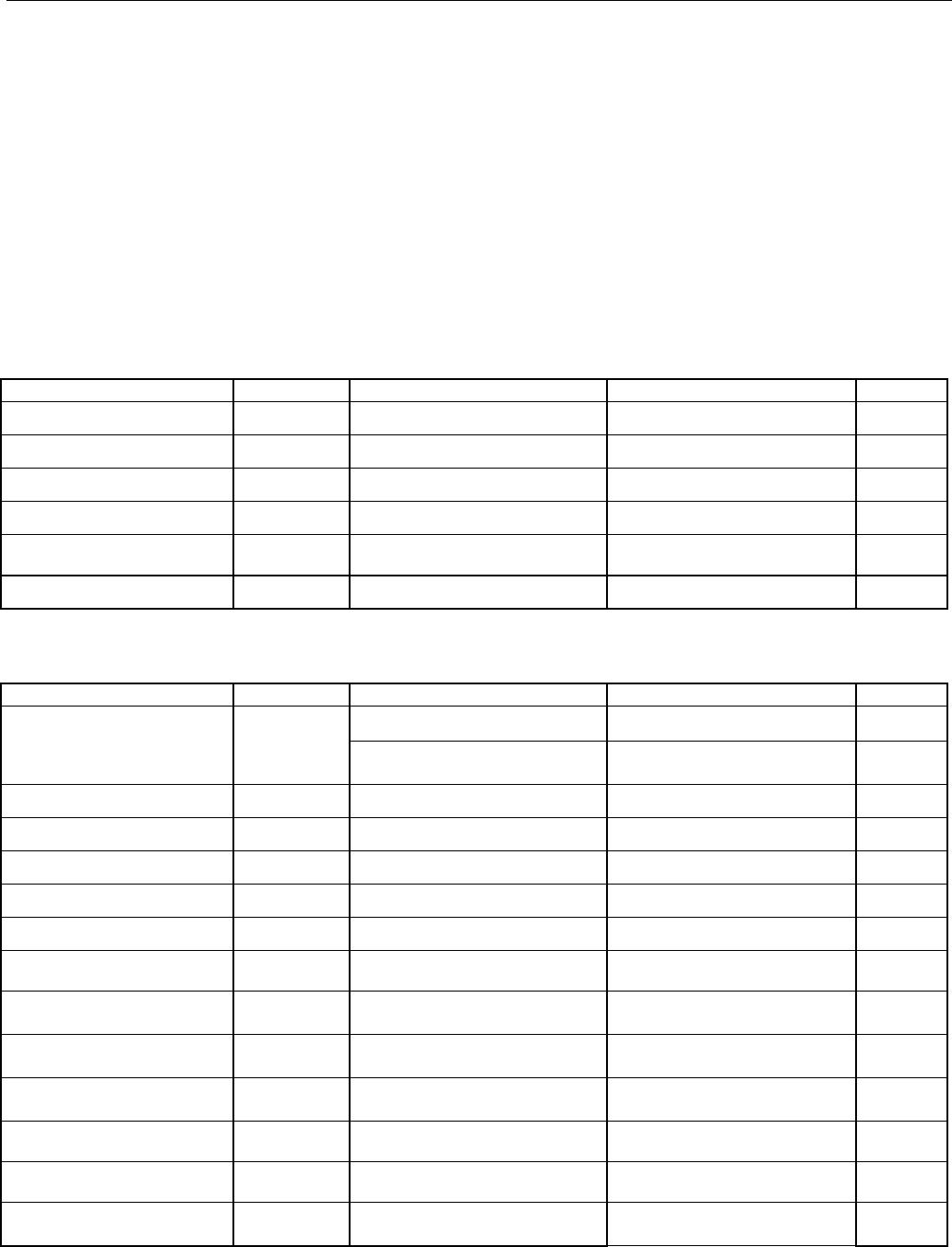
ORDERING INFORMATION
+ Denotes a lead(Pb)-free/RoHS-compliant package.
T&R = Tape and reel.
OPERATIONAL DIAGRAM
PART MARKING PIN-PACKAGE
DS2715Z+
D2715
16 SO
DS2715Z+T&R D2715 16 SO
DS2715BZ+ D2715B 16 SO
DS2715BZ+T&R D2715B 16 SO
DS2715
NiMH Battery Pack Charge Controlle
r
www.maxim-ic.com
See Table 1 for Ordering Information.
16 SO
C
BIAS
V
CH
V
SS
LED1
DNC
V
SS
CTG
CTG
V
BATT
THM
R
T
V
DD
SNS-
SNS+
DIV
MODE
19-4592; 4/09
DS2715: NiMH Battery Pack Charge Controller
ABSOLUTE MAXIMUM RATINGS*
Voltage on V
DD
and V
CH
Pins with Respect to V
SS
-0.3V to +18V
Voltage on LED1 Pin -0.3V to +18V
Voltage on SNS- -0.3V to +0.3V
Voltage on C
BIAS
-0.3V to 6V
Voltage on all Other Pins -0.3V to V
Cbias
Continuous Sink Current V
CH
and LED1 28mA
Operating Temperature Range -20°C to +85°C
Storage Temperature Range -55°C to +125°C
Soldering Temperature See IPC/JEDEC J-STD-020
Human Body Model (HBM) ESD Limit of V
CH
Pin 500V
HBM ESD Limit of all Other Pins 2KV
*This is a stress rating only and functional operation of the device at these or any other conditions above those indicated in the operation
sections of this specification is not implied. Exposure to absolute maximum rating conditions for extended periods of time may affect reliability.
RECOMMENDED DC OPERATING CONDITIONS
(4.5V V
DD
16.5V; T
A
= 0C to +70C.)
PARAMETER SYMBOL CONDITIONS MIN TYP MAX UNITS
Supply Voltage V
DD
(Note 1) 4.5 16.5 V
LED1 Voltage V
LED
(Note 1) 0.0 16.5 V
Mode Voltage V
MODE
(Note 1) 0.0 V
Cbias
V
V
CH
Voltage V
VCH
(Note 1) 0.0 16.5 V
C
BIAS
Capacitor Range C
Cbias
.02 .15 μF
R
T
Resistor Range R
Rt
20 240 K
DC ELECTRICAL CHARACTERISTICS
(4.5V V
DD
16.5V, T
A
= 0C to +70C, unless otherwise noted.)
PARAMETER SYMBOL CONDITIONS MIN TYP MAX UNITS
Linear Mode, V
DD
= 16.5V 1.3 1.6 mA
Operating Current
(Note 2)
I
DDA
Comparator Mode,
V
DD
= 16.5V
150 250 μA
Idle Current I
DDS
V
DD
< V
UVLO
10 μA
Discharge Current I
DDD
Discharge latch set (Note 2) 200 μA
UVLO Threshold V
UVLO
V
DD
Rising (Note 3) 3.8 3.9 4.0 V
UVLO Hysteresis V
UVLO-HYS
V
DD
Falling 35 mV
V
CH
Sink Current I
OL-Vch
V
OL
= 1.5V 20 mA
LED1 Sink Current I
OL-LED
V
OL
= 1.0V 20 mA
Leakage Current, V
CH
,
LED1
I
LKG
Pin Inactive or Device Idle -1 +1 μA
THM Pin Leakage
Current
I
LKG-THM
-1 +1 μA
V
BATT
Pin Leakage
Current
I
LKG-Vbatt
-50 +50 nA
C
BIAS
Voltage V
Cbias
0 < I
Cbias
< 0.4mA 3.9 4.0 4.3 V
DIV Pin Load Current I
Div
500 uA
Current Sense Amplifier
Gain
G
ERR
100μA < I
Vch
< 20mA 5 6.25 7.5
-1
DS2715: NiMH Battery Pack Charge Controller
PARAMETER SYMBOL CONDITIONS MIN TYP MAX UNITS
Current Sense
Comparator Gain
G
COMP
(Note 7) 10
-1
AC ELECTRICAL CHARACTERISTICS
(4.5V V
DD
16.5V, T
A
= 0C to +70C, unless otherwise noted.)
PARAMETER SYMBOL CONDITIONS MIN TYP MAX UNITS
UVLO Debounce Time t
UVLO
10 μs
Current Sense
Comparator Propagation
Delay
t
COMP
(Note 7) 250 ns
Discharge Detect
Propagation Delay
t
DD
From detection of current
reversal
1 μs
Return To Normal
Function (Op-Amp or
Comparator Mode)
t
RNF
Time from reset of discharge
latch
1 μs
R
T
Timing Accuracy t
Rt
(Note 4) -10 +10 %
Internal Clock Accuracy t
BASE
-10 +10 %
ELECTRICAL CHARACTERISTICS: CHARGING
(4.5V V
DD
16.5V, T
A
= 0C to +70C, unless otherwise noted.)
PARAMETER SYMBOL CONDITIONS MIN TYP MAX UNITS
FAST-CHARGE
Comparator Threshold
V
FC
FAST-CHARGE -127 -121 -115 mV
FAST-CHARGE
Comparator Hysteresis
V
HYS-FC
FAST-CHARGE 31 28 25 mV
TOPOFF and
PRECHARGE
Comparator Threshold
V
TO
TOPOFF and PRECHARGE -38 -33 -28 mV
TOPOFF and
PRECHARGE
Comparator Hysteresis
V
HYS-TO
TOPOFF and PRECHARGE 10 8 6 mV
Discharge Latch Reset
Threshold
V
DCHG-RST
-15 -10 -5 mV
Discharge Latch Set
Threshold
V
DCHG-SET
Reverse current through
sense resistor
5 10 15 mV
Low Battery Detect
Threshold
V
LB
From presence detect into
PRECHARGE
0.95 1.0 1.05 V
Cell Detect Threshold V
DET
1.50 1.55 1.60 V
No Cell Detect Threshold V
OPEN
1.60 1.65 1.70 V
Presence Detect
Threshold Hysteresis
V
HYS-PD
90 100 110 mV
2.88 2.92 2.96 V
Minimum Charge Temp V
THM-MIN
(Note 5, 6)
0 ºC
1.28 1.32 1.36 V
Maximum Charge Temp V
THM-MAX
(Note 5, 6)
45 ºC
1.12 1.16 1.20 V
Over Temp V
THM-STOP
(Note 5, 6)
50 ºC
dT/dt Detect T
TERM
0.425 0.5 0.575 ºC/min

DS2715BZ+

Mfr. #:
Manufacturer:
Maxim Integrated
Description:
Battery Management NiMH Battery Pack Charge Controller
Lifecycle:
New from this manufacturer.
Delivery:
DHL FedEx Ups TNT EMS
Payment:
T/T Paypal Visa MoneyGram Western Union

Products related to this Datasheet