R
o
H
S
Telecom Design Guide • © 2006 Littelfuse 3 - 27 www.littelfuse.com
SIDACtor Devices
T10B SIDACtor® Device
The bi-directional T10B devices are a through-hole technology SIDACtor protector. It is
intended for cost-sensitive telecommunication applications.
This T10 SIDACtor series enables equipment to comply with various regulatory
requirements including GR 1089, ITU K.20, K.21, and K.45, IEC 60950, UL 60950, and TIA-
968-A (formerly known as FCC Part 68).
* For surge ratings, see table below.
General Notes:
• All measurements are made at an ambient temperature of 25 °C. I
PP
applies to -40 °C through +85 °C temperature range.
• I
PP
is a repetitive surge rating and is guaranteed for the life of the product.
• Listed SIDACtor devices are bi-directional. All electrical parameters and surge ratings apply to forward and reverse polarities.
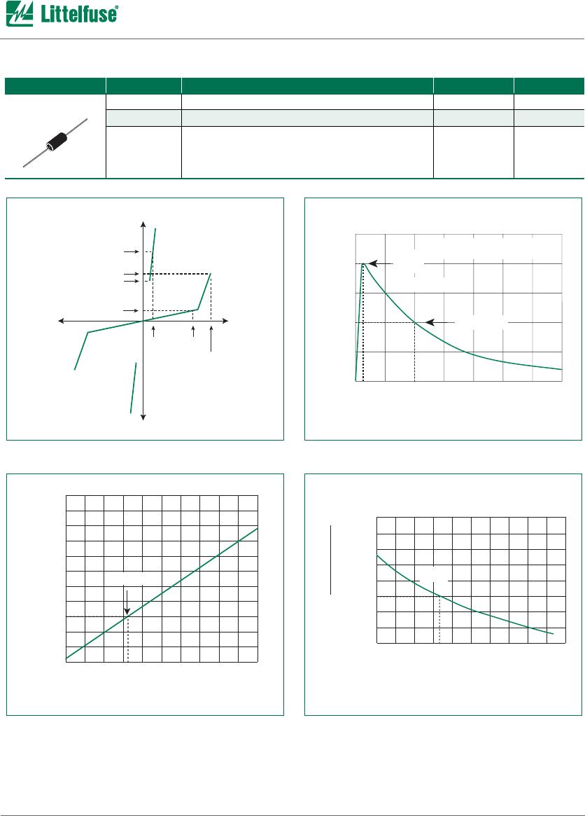
• V
DRM
is measured at I
DRM.
• V
S
is measured at 0.5 V/µs.
• Special voltage (V
S
and V
DRM
) and holding current (I
H
) requirements are available upon request.
* Current waveform in µs
** Voltage waveform in µs
Electrical Parameters
Part
Number *
V
DRM
@ 5 µA
Volts
V
S
Volts
V
T
Volts
I
S
mAmps
I
H
mAmps
pF
TYP
T10B080B 80 120 4 800 120 60
T10B080E 80 120 4 800 180 60
T10B110B 105 135 4 800 120 55
T10B110E 105 135 4 800 180 55
T10B140B 140 170 4 800 120 48
T10B140E 140 170 4 800 180 48
T10B180B 175 210 4 800 120 44
T10B180E 175 210 4 800 180 44
T10B220B 214 265 4 800 120 41
T10B220E 214 265 4 800 180 41
T10B270B 270 360 4 800 120 36
T10B270E 270 360 4 800 180 36
Surge Ratings in Amps
Series
I
PP
I
TSM
50 / 60 Hz di/dt
8x20 *
1.2x50 **
5x310 *
10x700 **
10x1000 *
10x1000 **
Amps Amps Amps Amps Amps/µs
B 250 125 100 50 100