BYV12, BYV13, BYV14, BYV15, BYV16
www.vishay.com
Vishay Semiconductors
Rev. 1.8, 04-Sep-12
1
Document Number: 86039
For technical questions within your region: DiodesAmericas@vishay.com
, DiodesAsia@vishay.com, DiodesEurope@vishay.com
THIS DOCUMENT IS SUBJECT TO CHANGE WITHOUT NOTICE. THE PRODUCTS DESCRIBED HEREIN AND THIS DOCUMENT
ARE SUBJECT TO SPECIFIC DISCLAIMERS, SET FORTH AT www.vishay.com/doc?91000
Fast Avalanche Sinterglass Diode
MECHANICAL DATA
Case: SOD-57
Terminals: plated axial leads, solderable per MIL-STD-750,
method 2026
Polarity: color band denotes cathode end
Mounting position: any
Weight: approx. 369 mg
FEATURES
• Glass passivated junction
• Hermetically sealed package
• Low reverse current
• Soft recovery characteristics
• Material categorization:
For definitions of compliance please see
www.vishay.com/doc?99912
APPLICATIONS
• Fast rectification and switching diode for example for
TV-line output circuits and switch mode power supply
ORDERING INFORMATION (Example)
DEVICE NAME ORDERING CODE TAPED UNITS MINIMUM ORDER QUANTITY
BYV16 BYV16-TR 5000 per 10" tape and reel 25 000
BYV16 BYV16-TAP 5000 per ammopack 25 000
PARTS TABLE
PART TYPE DIFFERENTIATION PACKAGE
BYV12 V
R
= 100 V; I
F(AV)
= 1.5 A SOD-57
BYV13 V
R
= 400 V; I
F(AV)
= 1.5 A SOD-57
BYV14 V
R
= 600 V; I
F(AV)
= 1.5 A SOD-57
BYV15 V
R
= 800 V; I
F(AV)
= 1.5 A SOD-57
BYV16 V
R
= 1000 V; I
F(AV)
= 1.5 A SOD-57
ABSOLUTE MAXIMUM RATINGS (T
amb
= 25 °C, unless otherwise specified)
PARAMETER TEST CONDITION PART SYMBOL VALUE UNIT
Reverse voltage = repetitive peak reverse
voltage
See electrical characteristics
BYV12 V
R
= V
RRM
100 V
BYV13 V
R
= V
RRM
400 V
BYV14 V
R
= V
RRM
600 V
BYV15 V
R
= V
RRM
800 V
BYV16 V
R
= V
RRM
1000 V
Peak forward surge current t
p
= 10 ms, half sine wave I
FSM
40 A
Repetitive peak forward current I
FRM
9A
Average forward current = 180° I
F(AV)
1.5 A
Non repetitive reverse avalanche energy I
(BR)R
= 0.4 A E
R
10 mJ
Junction and storage temperature range T
j
= T
stg
- 55 to + 175 °C
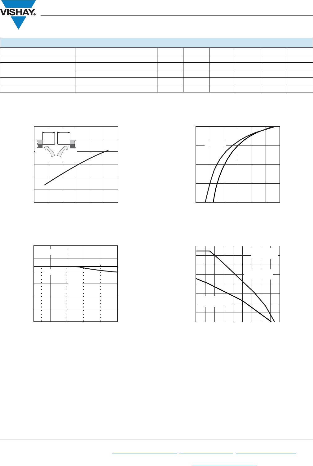
MAXIMUM THERMAL RESISTANCE (T
amb
= 25 °C, unless otherwise specified)
PARAMETER TEST CONDITION SYMBOL VALUE UNIT
Junction ambient
Lead length l = 10 mm, T
L
= constant R
thJA
45 K/W
On PC board with spacing 25 mm R
thJA
100 K/W