0.20
(.008)
0.50 ± 0.1
(.020 ± .004)
0.55 ± 0.1
(.022 ± .004)
0.40
(.016)
0.30
(.012)
1.00 ± 0.1
(.039 ± .004)
0.20
(.008)
0.50
(.020)
0.40
(.016)
0.50
(.020)
0.50
(.020)
Features
■ 0402 miniature size
■ Ceramic core provides stable electrical
characteristics
■ High Q
■ High self-resonant frequency
■ Flat top surface for automated assembly
■ RoHS compliant* and halogen free**
Applications
■ RF modules
■ Cellular phones
■ GPS receivers
■ Wireless PDAs, LANs
■ CATV fi lters, tuners
■ Cable modems, set-top boxes
CW100505 Series High Q Ceramic Chip Inductors
*RoHS Directive 2002/95/EC Jan. 27, 2003 including annex and RoHS Recast 2011/65/EU June 8, 2011.
** Bourns follows the prevailing defi nition of “halogen free” in the industry. Bourns considers a product to be “halogen free” if (a) the Bromine (Br) content is 900 ppm or less;
(b) the Chlorine (Cl) content is 900 ppm or less; and (c) the total Bromine (Br) and Chlorine (Cl) content is 1500 ppm or less.
Specifi cations are subject to change without notice.
The device characteristics and parameters in this data sheet can and do vary in different applications and actual device performance may vary over time.
Users should verify actual device performance in their specifi c applications.
Operating Temperature
................................-55 °C to +125 °C
(Temperature rise included)
Storage Temperature
................................-55 °C to +125 °C
Resistance to Soldering Heat
.......................... +260 °C, 5 sec. max.
Temperature Rise .....15 °C at rated Irms
Electrical Specifi cations
Bourns
®
Part No.
Inductance Q
Test Freq.
(MHz)
SRF
(MHz)
DCR
(Ohms)
Irms
(mA)
L (nH) Tol. Min. L / Q Min. Max.
CW100505-1N0D 1.0 ±0.3 nH 13 250 6000 0.045 1360
CW100505-2N2D 2.2 ±0.3 nH 18 250 6000 0.070 960
CW100505-2N7D 2.7 ±0.3 nH 16 250 6000 0.120 640
CW100505-3N3J 3.3 ±5 % 20 250 6000 0.066 840
CW100505-3N9J 3.9 ±5 % 20 250 5800 0.066 840
CW100505-4N7J 4.7 ±5 % 15 250 4775 0.130 640
CW100505-5N6J 5.6 ±5 % 23 250 5800 0.083 760
CW100505-6N8J 6.8 ±5 % 20 250 4800 0.083 680
CW100505-8N2J 8.2 ±5 % 25 250 4400 0.104 680
CW100505-10NJ 10.0 ±5 % 23 250 3900 0.195 480
CW100505-12NJ 12.0 ±5 % 26 250 3600 0.120 640
CW100505-15NJ 15.0 ±5 % 26 250 3280 0.172 560
CW100505-18NJ 18.0 ±5 % 25 250 3100 0.230 420
CW100505-22NJ 22.0 ±5 % 25 250 2800 0.300 400
CW100505-27NJ 27.0 ±5 % 26 250 2480 0.298 400
CW100505-33NJ 33.0 ±5 % 24 250 2350 0.350 400
CW100505-39NJ 39.0 ±5 % 25 250 2100 0.550 320
CW100505-47NJ 47.0 ±5 % 26 200 2100 0.830 210
CW100505-56NJ 56.0 ±5 % 22 200 1760 0.970 200
CW100505-68NJ 68.0 ±5 % 22 200 1620 1.120 180
CW100505-82NJ 82.0 ±5 % 20 150 1500 1.250 150
CW100505-R10J 100.0 ±5 % 20 150 1300 2.520 120
CW100505-R12J 120.0 ±5 % 20 150 1100 2.660 110
General Specifi cations
Core ...........................................Ceramic
Wire ............Enameled copper (Class H)
Terminal ........................... Mo/Mn+Ni+Au
Packaging .... 10,000 pcs. per 7-inch reel
Materials
Product Dimensions
*RoHS COMPLIANT
DIMENSIONS:
MM
(INCHES)
Recommended Layout
Schematic
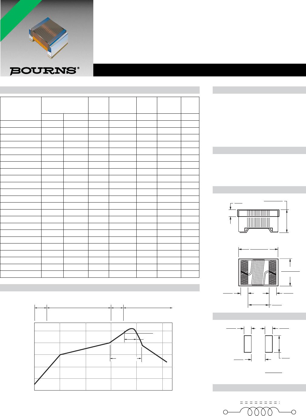
Soldering Profi le
0
Time (Seconds)
Temperature (°C)
50
100
150
200
250
50 100 150 200 250
70 SECONDS MAX.
Temperature
Rising
Area
4 °C/
Sec.
Max.
-
50 SECONDS MAX.
PEAK TEMP.
260 °C
230 °C
-
-
Preheat
Area
150~200 °C / 60~120 Sec.
-
Reflow
Area
20~
40 °C/
Sec.
Max.
-
Forced Cooling
Area
-1~5 °C/Sec. Max.
