BAT54W_SER All information provided in this document is subject to legal disclaimers. © NXP B.V. 2012. All rights reserved.
Product data sheet Rev. 3 — 20 November 2012 3 of 11
NXP Semiconductors
BAT54W series
Schottky barrier diodes
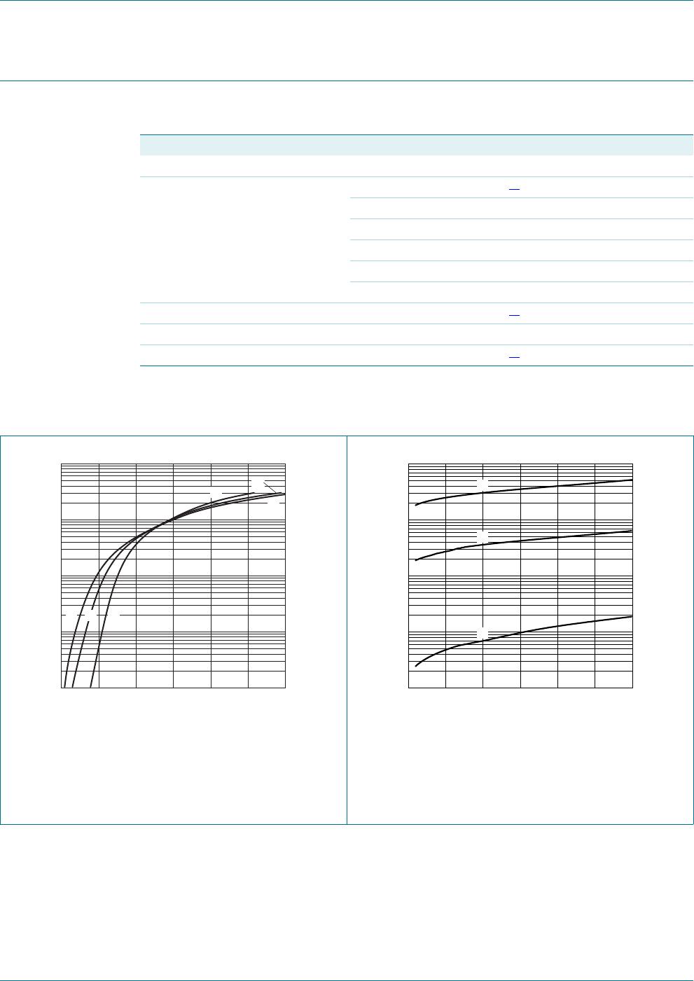
5. Limiting values
[1] T
j
=25C before surge.
[2] Device mounted on an FR4 Printed-Circuit Board (PCB), single-sided copper, tin-plated and standard
footprint.
6. Thermal characteristics
[1] Device mounted on an FR4 PCB, single-sided copper, tin-plated and standard footprint.
Table 5. Limiting values
In accordance with the Absolute Maximum Rating System (IEC 60134).
Symbol Parameter Conditions Min Max Unit
Per diode
V
R
reverse voltage - 30 V
I
F
forward current - 200 mA
I
FRM
repetitive peak forward
current
t
p
1s; 0.5 300 mA
I
FSM
non-repetitive peak
forward current
square wave;
t
p
<10ms
[1]
-600mA
Per device; one diode loaded
P
tot
total power dissipation T
amb
25 C
[2]
-200mW
T
j
junction temperature - 150 C
T
amb
ambient temperature 55 +150 C
T
stg
storage temperature 65 +150 C
Table 6. Thermal characteristics
Symbol Parameter Conditions Min Typ Max Unit
Per device; one diode loaded
R
th(j-a)
thermal resistance from
junction to ambient
in free air
[1]
- - 625 K/W