BATTERY PROTECTION IC FOR 1-SERIAL TO 4-SERIAL-CELL PACK (SECONDARY PROTECTION)
Rev.6.1_00
S-8244 Series
Seiko Instruments Inc.
9
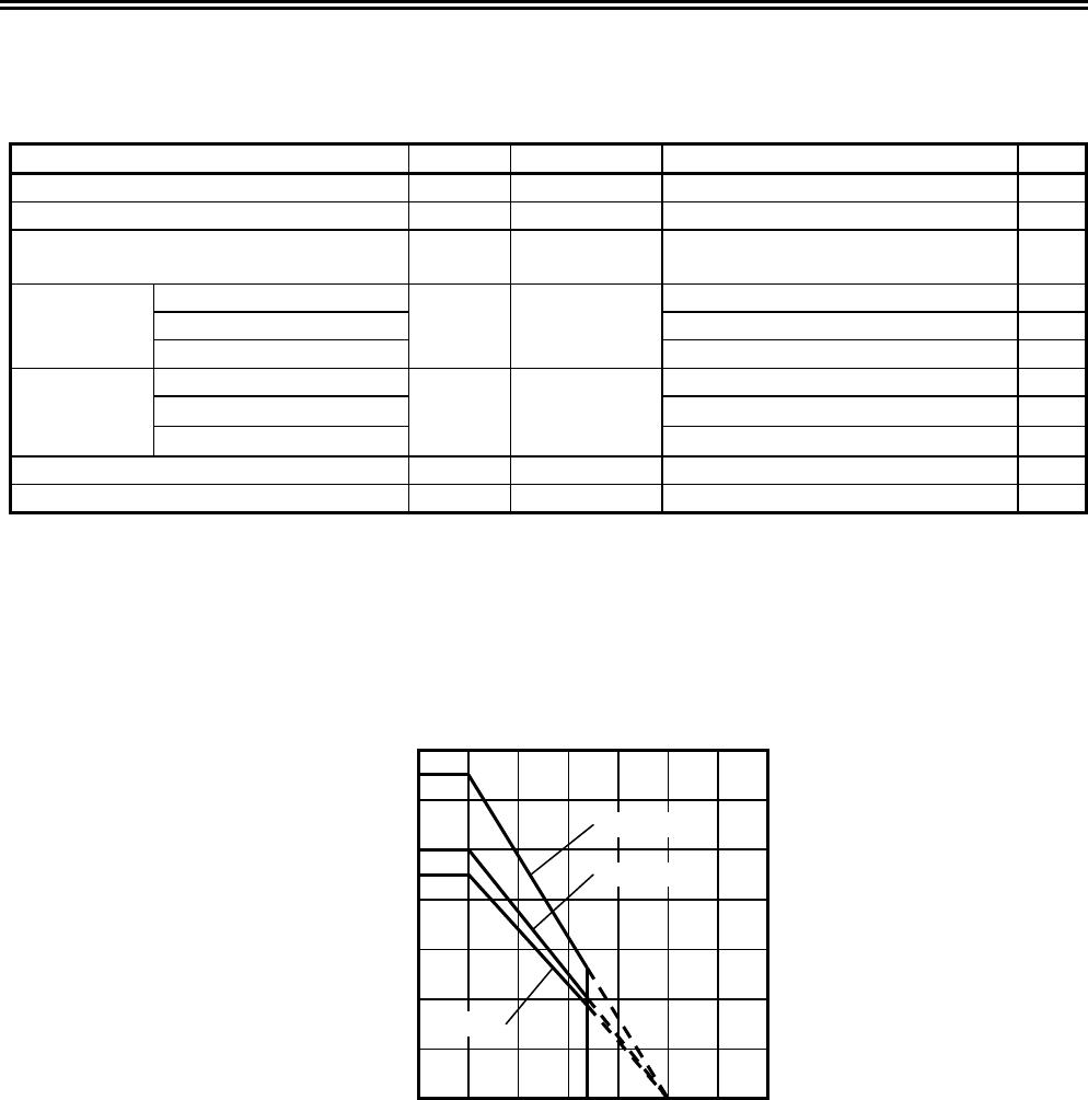
Test Circuits
(1) Test Condition 1, Test Circuit 1
Set switches 1 and 2 to OFF for CMOS output product.
Set switch 1 to ON and switch 2 to OFF for Nch open drain product.
Set switch 1 to OFF and switch 2 to ON for Pch open drain product.
• Product with CMOS output active “H”, Nch open drain output active “H”
The overcharge detection voltage 1 (V
CU1
) is a voltage at V1; when the CO pin’s voltage is set to “H” by increasing
V1 gradually, after setting V1 = V2 = V3 = V4 = 3.5 V. After that, gradually decreasing V1’s voltage to set CO = “L”,
and the difference of this V1’s voltage and V
CU1
is the overcharge hysteresis voltage 1 (V
CD1
).
• Product with CMOS output active “L”, Nch open drain output active “L”, Pch open drain output active “L”
The overcharge detection voltage 1 (V
CU1
) is a voltage at V1; when the CO pin’s voltage is set to “L” by increasing
V1 gradually, after setting V1 = V2 = V3 = V4 = 3.5 V. After that, gradually decreasing V1’s voltage to set CO =
“H”, and the difference of this V1’s voltage and V
CU1
is the overcharge hysteresis voltage 1 (V
CD1
).
(2) Test Condition 2, Test Circuit 1
Set switches 1 and 2 to OFF for CMOS output product.
Set switch 1 to ON and switch 2 to OFF for Nch open drain product.
Set switch 1 to OFF and switch 2 to ON for Pch open drain product.
• Product with CMOS output active “H”, Nch open drain output active “H”
The overcharge detection voltage 2 (V
CU2
) is a voltage at V2; when the CO pin’s voltage is set to “H” by increasing
V2 gradually, after setting V1 = V2 = V3 = V4 = 3.5 V. After that, gradually decreasing V2’s voltage to set CO = “L”,
and the difference of this V2’s voltage and V
CU2
is the overcharge hysteresis voltage 2 (V
CD2
).
• Product with CMOS output active “L”, Nch open drain output active “L”, Pch open drain output active “L”
The overcharge detection voltage 2 (V
CU2
) is a voltage at V2; when the CO pin’s voltage is set to “L” by increasing
V2 gradually, after setting V1 = V2 = V3 = V4 = 3.5 V. After that, gradually decreasing V2’s voltage to set CO =
“H”, and the difference of this V2’s voltage and V
CU2
is the overcharge hysteresis voltage 2 (V
CD2
).
(3) Test Condition 3, Test Circuit 1
Set switches 1 and 2 to OFF for CMOS output product.
Set switch 1 to ON and switch 2 to OFF for Nch open drain product.
Set switch 1 to OFF and switch 2 to ON for Pch open drain product.
• Product with CMOS output active “H”, Nch open drain output active “H”
The overcharge detection voltage 3 (V
CU3
) is a voltage at V3; when the CO pin’s voltage is set to “H” by increasing
V3 gradually, after setting V1 = V2 = V3 = V4 = 3.5 V. After that, gradually decreasing V3’s voltage to set CO = “L”,
and the difference of this V3’s voltage and V
CU3
is the overcharge hysteresis voltage 3 (V
CD3
).
• Product with CMOS output active “L”, Nch open drain output active “L”, Pch open drain output active “L”
The overcharge detection voltage 3 (V
CU3
) is a voltage at V3; when the CO pin’s voltage is set to “L” by increasing
V3 gradually, after setting V1 = V2 = V3 = V4 = 3.5 V. After that, gradually decreasing V3’s voltage to set CO =
“H”, and the difference of this V3’s voltage and V
CU3
is the overcharge hysteresis voltage 3 (V
CD3
).