BTA26-600BRG

July 2007 Rev 10 1/12
12
BTA24, BTB24, BTA25
BTA26, BTB26, T25
25 A standard and Snubberless™ triacs
Features
High current triac
Low thermal resistance with clip bonding
High commutation (4 quadrant) or very high
commutation (3 quadrant) capability
BTA series UL1557 certified (File ref: 81734)
Packages are RoHS (2002/95/EC) compliant
Applications
Applications include the ON/OFF function in
applications such as static relays, heating
regulation, induction motor starting circuits, etc.,
or for phase control operation in light dimmers,
motor speed controllers, and silmilar.
The snubberless versions (BTA/BTB...W and T25
series) are especially recommended for use on
inductive loads, due to their high commutation
performances. The BTA series provides an
insulated tab (rated at 2500 V
RMS
).
Description
Available either in through-hole or surface-mount
packages, the BTA24, BTB24, BTA25, BTA26,
BTB26 and T25 triac series is suitable for general
purpose mains power AC switching.
TM: Snubberless is a trademark of STMicroelectronics
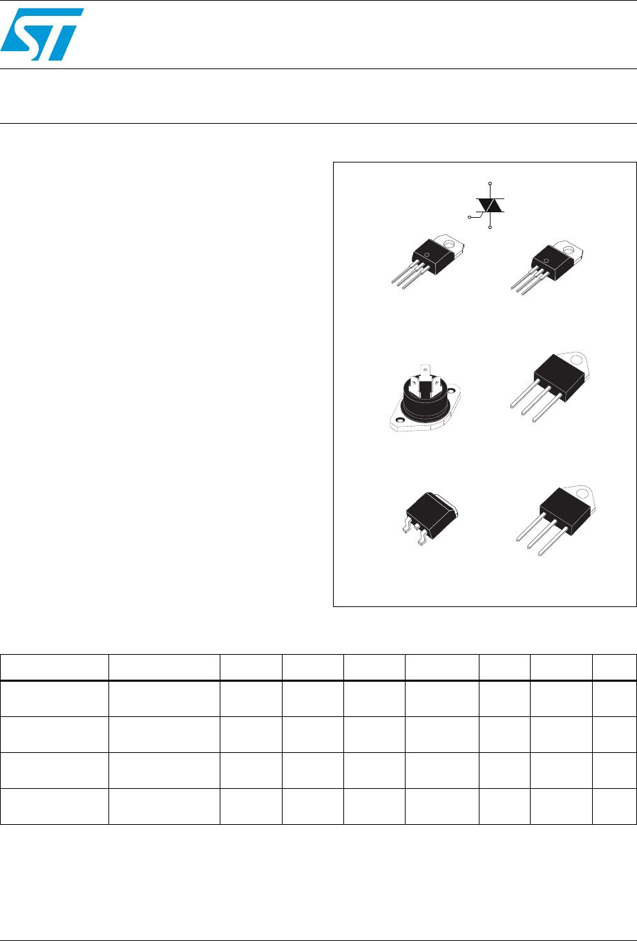
D
2
PAK
(T25)
RD91
(BTA25)
TOP3 Insulated
(BTA26)
TO-220AB Insulated
(BTA24)
TO-220AB
(BTB24)
G
A2
A1
G
A2
A2
A1
A2
A1
G
G
A2
A1
G
A2
A1
A2
A2
G
A1
TOP3
(BTB26)
G
A2
A1
A2
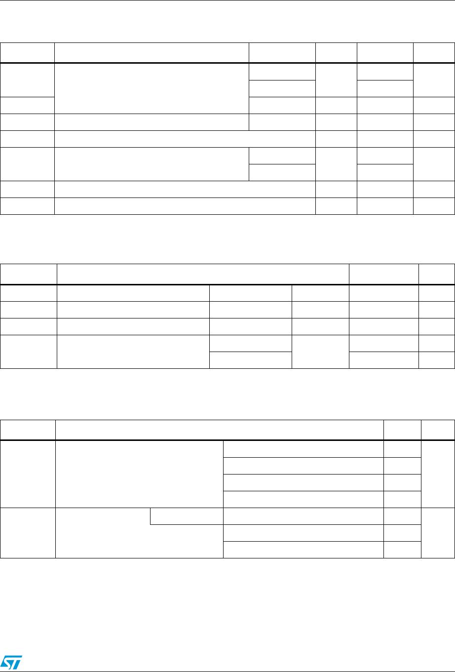
Table 1. Device summary
Symbol Parameter BTA24
(1)
1. Insulated packages
BTB24 BTA25
(1)
BTA26
(1)
BTB26 T25 Unit
I
T(RMS)
RMS on-state
current
25 25 25 25 25 25 A
V
DRM
/V
RRM
Repetitive peak
off-state voltage
600 / 800 600 / 800 600 / 800 600
(2)
/ 800
2. 600 V version available only with I
GT
= 50 mA (Snubberless and Standard)
600 600 / 800 V
I
GT
(Snubberless)
Triggering gate
current
35 / 50 35 / 50 50 35 / 50 - 35 mA
I
GT
(Standard)
Triggering gate
current
-50505050-mA
www.st.com
Characteristics BTA24, BTB24, BTA25, BTA26, BTB26, T25
2/12
1 Characteristics
Table 2. Absolute maximum ratings
Symbol Parameter Value Unit
I
T(RMS)
RMS on-state current (full sine wave)
TOP3 T
c
= 105° C
25 A
D
2
PAK /
TO-220AB
T
c
= 100° C
RD91 Ins/
TOP3 Ins.
T
c
= 100° C
TO-220AB Ins. T
c
= 75° C
I
TSM
Non repetitive surge peak on-state
current (full cycle, T
j
initial = 25° C)
F = 50 Hz t = 20 ms 250
A
F = 60 Hz t = 16.7 ms 260
I
²
tI
²
t Value for fusing t
p
= 10 ms 340 A
²
s
dI/dt
Critical rate of rise of on-state current
I
G
= 2 x I
GT
, t
r
100 ns
F = 120 Hz T
j
= 125° C 50 A/µs
V
DSM
/V
RSM
Non repetitive surge peak off-state
voltage
t
p
= 10 ms T
j
= 25° C
V
DRM
/V
RRM
+ 100
V
I
GM
Peak gate current t
p
= 20 µs T
j
= 125° C 4 A
P
G(AV)
Average gate power dissipation T
j
= 125° C 1 W
T
stg
T
j
Storage junction temperature range
Operating junction temperature range
- 40 to + 150
- 40 to + 125
° C
Table 3. Electrical characteristics (T
j
= 25° C, unless otherwise specified), Snubberless and
logic level (3 quadrants) T25, BTA/BTB24...W, BTA25...W, BTA26...W
Symbol Test Conditions Quadrant
T25 BTA/BTB
Unit
T2535 CW BW
I
GT
(1)
V
D
= 12 V R
L
= 33 Ω
I - II - III MAX. 35 35 50 mA
V
GT
I - II - III MAX. 1.3 V
V
GD
V
D
= V
DRM
R
L
= 3.3 kΩ
T
j
= 125° C
I - II - III MIN. 0.2 V
I
H
(2)
I
T
= 500 mA MAX. 50 50 75 mA
I
L
I
G
= 1.2 I
GT
I - III
MAX.
70 70 80
mA
II 80 80 100
dV/dt
(2)
V
D
= 67 %V
DRM
gate open T
j
= 125° C MIN. 500 500 1000 V/µs
(dI/dt)c
(2)
Without snubber T
j
= 125° C MIN. 13 13 22 A/ms
1. minimum I
GT
is guaranted at 5% of I
GT
max.
2. for both polarities of A2 referenced to A1.
BTA24, BTB24, BTA25, BTA26, BTB26, T25 Characteristics
3/12
Table 4. Electrical characteristics (T
j
= 25° C, unless otherwise specified),
standard (4 quadrants), BTB24...B, BTA25...B, BTA26...B, BTB26...B
Symbol Test Conditions Quadrant Value Unit
I
GT
(1)
V
D
= 12 V R
L
= 33 Ω
I - II - III
MAX.
50
mA
IV 100
V
GT
ALL MAX. 1.3 V
V
GD
V
D
= V
DRM
R
L
= 3.3 kΩ T
j
= 125° C ALL MIN. 0.2 V
I
H
(2)
)I
T
= 500 mA MAX. 80 mA
I
L
I
G
= 1.2 I
GT
I - III - IV
MAX.
70
mA
II 160
dV/dt
(2)
V
D
= 67 %V
DRM
gate open T
j
= 125° C MIN. 500 V/µs
(dV/dt)c
(2)
(dI/dt)c = 13.3 A/ms T
j
= 125° C MIN. 10 V/µs
1. minimum I
GT
is guaranted at 5% of I
GT
max.
2. for both polarities of A2 referenced to A1.
Table 5. Static characteristics
Symbol Test Conditions Value Unit
V
TM
(1)
I
TM
= 35 A t
p
= 380 µs T
j
= 25° C MAX. 1.55 V
V
t0
(1)
Threshold voltage T
j
= 125° C MAX. 0.85 V
R
d
(1)
Dynamic resistance T
j
= 125° C MAX. 16 mΩ
I
DRM
I
RRM
V
DRM
= V
RRM
T
j
= 25° C
MAX.
A
T
j
= 125° C 3 mA
1. for both polarities of A2 referenced to A1.
Table 6. Thermal resistance
Symbol Parameter Value Unit
R
th(j-c)
Junction to case (AC)
TOP 3 0.6
° C/W
D
2
PAK / TO-220AB 0.8
RD91 Insulated / TOP3 Insulated 0.9
TO-220AB Insulated 1.7
R
th(j-a)
Junction to ambient
(1)
S = 1 cm
²
D
2
PA K 4 5
° C/WTOP3 / TOP3 Insulated 50
TO-220AB / TO-220AB Insulated 60
1. S = Copper surface under tab.

BTA26-600BRG

Mfr. #:
Manufacturer:
STMicroelectronics
Description:
Triacs 25 Amp 600 Volt
Lifecycle:
New from this manufacturer.
Delivery:
DHL FedEx Ups TNT EMS
Payment:
T/T Paypal Visa MoneyGram Western Union