3
3M
™
Thermally Conductive Acrylic Interface Pad 5571
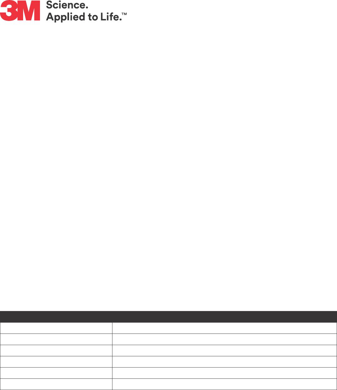
Compression vs. Stress
(2)
3M
™
Thermally Conductive Acrylic Interface Pad 5571
Application Techniques
• To obtain optimum thermal conductivity, good surfaces for wet out are required. For better contact,
clean, dry and well unied surface conditions are recommended. Typical surface cleaning solvents are
isopropyl alcohol and water (rubbing alcohol) or heptane. Note: Be sure to follow manufacturer’s safety
precautions and directions for use when using solvents.
• Ideal application temperature range is from 0°C to 40°C. Initial application to surfaces at temperatures
below 30°C is not recommended because the pad becomes too rm to be wet out readily. However,
once properly applied, low temperature holding is generally satisfactory.
Heat Resistance
*Note: The end use customer application, design & verication testing will determine the nal in use eective temperature range based
on each application’s environmental conditions.
Duration (hrs) Initial 1000 2000 5000
Thermal Conductivity (W/mK) 2.0 2.0 2.0 2.0
Hardness (Shore 00) 69 70 70 70
Appearance – No effect No effect No effect
Typical Physical Properties and Performance Characteristics
Note: The following technical information and data should be considered representative or typical only and should not be used for
specication purposes. Final product specications and testing methods will be outlined in the products Certicate of Analysis
(COA) that is provided once the product is approved by 3M for general commercialization and development work is completed.
a
Methods listed as ASTM are tested in accordance with the ASTM method noted
b
Thermal Conductivity Test Methods:
• 2.0W/m-K in XY direction per Hot wire plane Test method (Test equipment: QTM-500)
• 2.0W/m-K in Z direction tested in accordance with a simplied ASTM D5470 type method (Test equipment: Tester DynTIM)
3M™ Thermally Conductive Acrylic Interface Pad 5571
Property Method
a
0.75T 1.0T 1.5T 2.0T
Thickness (mm) – 0.75 1.0 1.5 2.0
Thermal conductivity (W/mK)
b
ASTM C1113 2.0
Hardness (Shore 00) TS-KOR-217 70
Density (grams/cm
3
) TS-TM-44 1.85
Flammability UL94 V-0
Dielectric Strength (kV/mm) ASTM D149 13
Volume Resistivity (Ω-cm) JIS K6249 3.3 x 10
12
Compression vs. Stress
80
60
40
20
0
0 2 4 6 8 10 12
Stress [kg/cm
2
)
Compression [%]
• Sample size: 1.0T, 30 by 30mm
• Test speed: 0.5mm/min
80
60
40
20
0
0 2 4 6 8 10 12
Stress [kg/cm
2
)
Sample size: 1.0T, 30 by 30mm
Test speed: 0.5mm/min
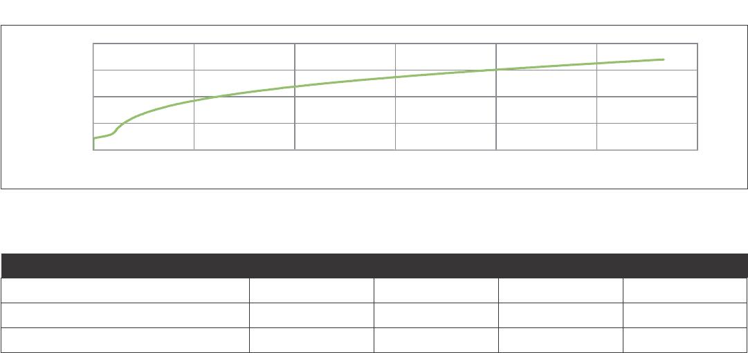
Heat Resistance
1, 2
Duration (hrs) Initial 1000 2000 5000
Thermal Conductivity (W/mK) 2.0 2.0 2.0 2.0
Hardness (Shore 00) 69 70 70 70
Appearance – No eect No eect No eect
1
Aged by dwelling at 110°C high temperature chamber.
2
The end use customer application, design and verication testing will determine the nal in-use eective temperature range based on each
application’s environmental conditions.
Certicate of Analysis (COA)
The 3M Certicate of Analysis (COA) for this product is established when the product becomes commercially available
from 3M. The Technical Data Sheet (TDS) technical information, test methods and data should be considered represen-
tative or typical only and should not be used for specication purposes. The Technical Data Sheet (TDS) information is
based on a limited set of test results and do not reect the COA specication limits. Final product specications and
associated manufacturing facility testing methods used for the commercialized product are outlined in the products
Certicate of Analysis (COA) that is provided upon request or with the products shipment.
The COA contains the 3M specications and test methods for the products performance limits that the product will be
supplied against. The 3M product is supplied to 3M COA test specications and the COA test methods. Contact your
local 3M Technical Service representative for the COA for this product.
Storage and Shelf Life
The shelf life of 3M
™
Thermally Conductive Acrylic Interface Pad 5571 is 12 months from the date of manufacture when
stored in the original packaging materials and stored at 21°C (70°F) and 50% relative humidity.