LTC1446LCS8#TRPBF

7
LTC1446/LTC1446L
Resolution (n)
Resolution is defined as the number of digital input bits,
n. It defines the number of DAC output states (2
n
) that
divide the full-scale range. The resolution does not imply
linearity.
Full-Scale Voltage (V
FS
)
This is the output of the DAC when all bits are set to one.
Voltage Offset Error (V
OS
)
The theoretical voltage at the output when the DAC is
loaded with all zeros. The output amplifier can have a true
negative offset, but because the part is operated from a
single supply, the output cannot go below zero. If the
offset is negative, the output will remain near 0V resulting
in the transfer curve shown in Figure 1.
Nominal LSBs:
LTC1446 LSB = 4.095V/4095 = 1mV
LTC1446L LSB = 2.5V/4095 = 0.610mV
Zero Scale Error (ZSE)
The output voltage when the DAC is loaded with all zeros.
Since this is a single supply part this value cannot be less
than 0V.
Integral Nonlinearity (INL)
End-point INL is the maximum deviation from a straight
line passing through the end points of the DAC transfer
curve. Because the part operates from a single supply and
the output cannot go below 0, the linearity is measured
between full scale and the code corresponding to the
maximum offset specification. The INL error at a given
input code is calculated as follows :
INL = [V
OUT
– V
OS
– (V
FS
– V
OS
)(Code/4095)]/LSB
V
OUT
= the output voltage of the DAC measured at the given
input code
Differential Nonlinearity (DNL)
DNL is the difference between the measured change and
the ideal 1LSB change between any two adjacent codes.
The DNL error between any two codes is calculated as
follows:
DNL = (V
OUT
– LSB)/LSB
V
OUT
= The measured voltage difference between two
adjacent codes
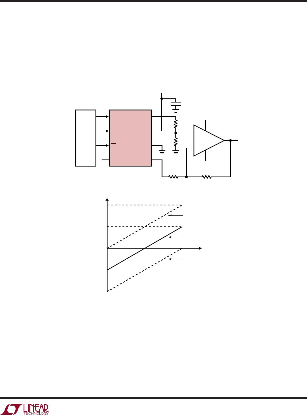
Figure 1. Effect of Negative Offset
DAC CODE
1446/46L F01
OUTPUT
VOLTAGE
NEGATIVE
OFFSET
0V
DEFI ITIO S
UU
The offset of the part is measured at the code that corre-
sponds to the maximum offset specification:
V
OS
= V
OUT
– [(Code)(V
FS
)/(2
n
– 1)]
Least Significant Bit (LSB)
One LSB is the ideal voltage difference between two
successive codes.
LSB = (V
FS
– V
OS
)/(2
n
– 1) = (V
FS
– V
OS
)/4095
8
LTC1446/LTC1446L
Serial Interface
The data on the D
IN
input is loaded into the shift register
on the rising edge of the clock. Data is loaded as one 24-
bit word where the first 12 bits are for DAC A and the
second 12 are for DAC B. For each 12-bit segment the MSB
is loaded first. Data from the shift register is loaded into the
DAC register when CS/LD is pulled high. The clock is
disabled internally when CS/LD is high. Note: CLK must be
low before CS/LD is pulled low to avoid an extra internal
clock pulse.
The buffered output of the 24-bit shift register is available
on the D
OUT
pin which swings from GND to V
CC
.
Multiple LTC1446/LTC1446L’s may be daisy-chained to-
gether by connecting the D
OUT
pin to the D
IN
pin of the next
chip, while the clock and CS/LD signals remain common
to all chips in the daisy chain. The serial data is clocked to
all of the chips, then the CS/LD signal is pulled high to
update all of them simultaneously.
OPERATIO
U
Voltage Output
The LTC1446/LTC1446L include an internal voltage refer-
ence which is connected to each DAC. The LTC1446 has a
full scale of 4.095V making 1LSB equal to 1mV. The
LTC1446L has a full scale of 2.5V making 1LSB equal to
0.61mV.
The LTC1446/LTC1446L rail-to-rail buffered outputs can
source or sink 5mA when operating with a 5V supply while
pulling to within 300mV of the positive supply voltage or
ground. The outputs swing to within a few millivolts of
either supply rail when unloaded and have an equivalent
output resistance of 40 when driving a load to the rails.
The buffer amplifiers can drive 1000pF without going into
oscillation. The output noise spectral density is
600nV/Hz at 1kHz.
9
LTC1446/LTC1446L
TYPICAL APPLICATIONS N
U
LTC1446
50k
5V
15V
–15V
CLK
0.1µF
50k
µP
CS/LD
D
IN
D
OUT
V
OUT B
GND
V
CC
V
OUT A
V
OUT
8.190
D
IN
A
A: V
OUT A
0V
B: V
OUT A
2.048V
C: V
OUT A
4.095V
4.094
0
–4.096
–8.190
1446/46L F02
V
OUT
=
2 (V
OUT B
– V
OUT A)
100k
100k
+
LT1077
B
C
A Wide Swing, Bipolar Output DAC with Digitally Controlled Offset
This circuit shows how to use an LTC1446 and an
LT
®
1077 to make a wide bipolar output swing 12-bit DAC
with an offset that can be digitally programmed. V
OUT A
,
which can be set by loading the appropriate digital code
for DAC A, sets the offset. As this value changes, the
transfer curve for the output moves up and down as
illustrated in the graph below.

LTC1446LCS8#TRPBF

Mfr. #:
Manufacturer:
Analog Devices Inc.
Description:
Digital to Analog Converters - DAC 3V Dual 12-Bit Vout DAC in S08
Lifecycle:
New from this manufacturer.
Delivery:
DHL FedEx Ups TNT EMS
Payment:
T/T Paypal Visa MoneyGram Western Union