ADuM2200/ADuM2201 Data Sheet
Rev. G | Page 10 of 17
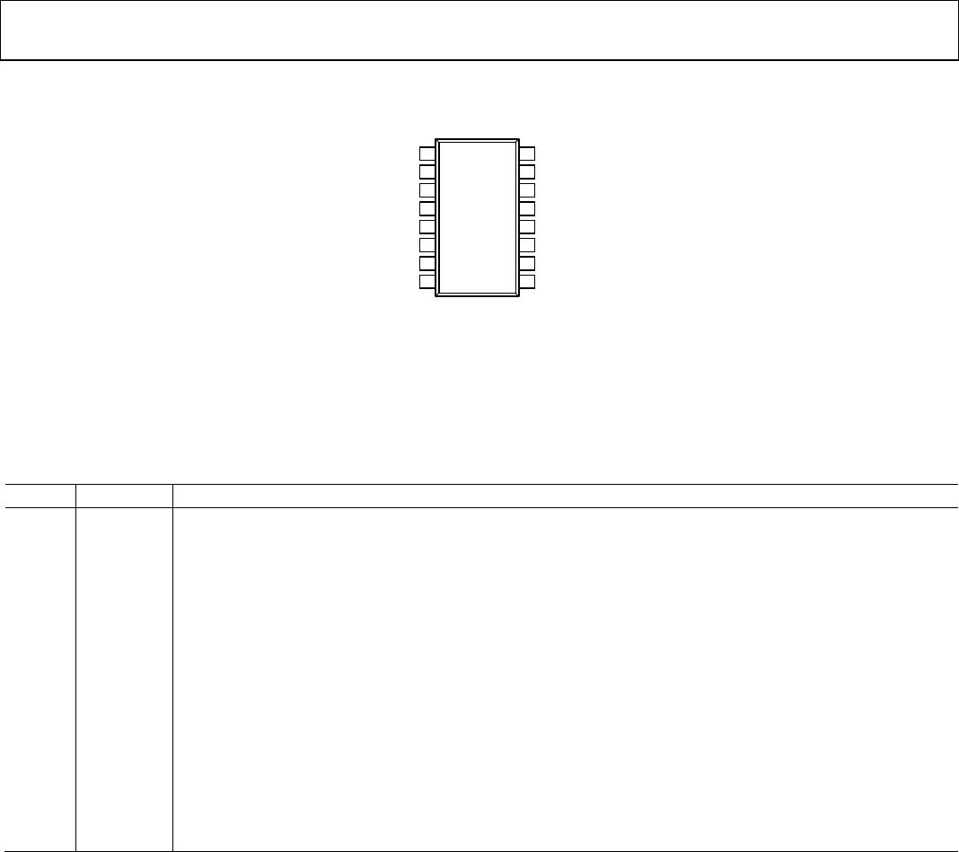
PIN CONFIGURATIONS AND FUNCTION DESCRIPTIONS
GND
1
1
NC
2
V
DD1
3
V
IA
4
GND
2
16
NC
15
V
DD2
14
V
OA
13
V
IB
5
V
OB
12
NC
6
NC
11
GND
1
7
NC
10
NC
8
GND
2
9
NC = NO CONNECT
NOTES:
1. PIN 1 AND PIN 7 ARE INTERNALLY CONNECTED TO EACH OTHER, AND
IT IS RECOMMENDED THA
T BOTH PINS BE CONNECTED
TO
A COMMON GROUND.
2. PIN 9
AND PIN 16 ARE INTERNALLY CONNECTED TO EACH OTHER, AND
IT IS RECOMMENDED THAT BOTH PINS BE CONNECTED
TO
A
COMMON GROUND.
ADuM2200
TOP VIEW
(Not to Scale)
07235-004
Figure 4. ADuM2200 Pin Configuration
Table 22. ADuM2200 Pin Function Descriptions
Pin No. Mnemonic Description
1, 7 GND
1
Ground 1. Ground reference for Isolator Side 1. Pin 1 and Pin 7 are internally connected to each other, and it is
recommended that both pins be connected to a common ground.
2 NC No Internal Connection.
3 V
Supply Voltage for Isolator Side 1, 3.0 V to 5.5 V.
4 V
Logic Input A.
5 V
Logic Input B.
6 NC No Internal Connection.
8 NC No Internal Connection.
9, 16 GND
2
Ground 2. Ground reference for Isolator Side 2. Pin 9 and Pin 16 are internally connected to each other, and it is
recommended that both pins be connected to a common ground.
10 NC No Internal Connection.
11 NC No Internal Connection.
12 V
Logic Output B.
13 V
Logic Output A.
14 V
Supply Voltage for Isolator Side 2, 3.0 V to 5.5 V.
15 NC No Internal Connection.