CAT1021, CAT1022, CAT1023
www.onsemi.com
10
ACKNOWLEDGE
After a successful data transfer, each receiving device is
required to generate an acknowledge. The acknowledging
device pulls down the SDA line during the ninth clock cycle,
signaling that it received the 8 bits of data.
All devices respond with an acknowledge after receiving
a START condition and its slave address. If the device has
been selected along with a write operation, it responds with
an acknowledge after receiving each 8bit byte.
When a device begins a READ mode it transmits 8 bits of
data, releases the SDA line and monitors the line for an
acknowledge. Once it receives this acknowledge, the device
will continue to transmit data. If no acknowledge is sent by
the Master, the device terminates data transmission and
waits for a STOP condition.
WRITE OPERATIONS
Byte Write
In the Byte Write mode, the Master device sends the
START condition and the slave address information (with
the R/W
bit set to zero) to the Slave device. After the Slave
generates an acknowledge, the Master sends a 8bit address
that is to be written into the address pointers of the device.
After receiving another acknowledge from the Slave, the
Master device transmits the data to be written into the
addressed memory location. The device acknowledges once
more and the Master generates the STOP condition. At this
time, the device begins an internal programming cycle to
nonvolatile memory. While the cycle is in progress, the
device will not respond to any request from the Master
device.
Figure 5. Start/Stop Timing
START BIT
A
SD
STOP BIT
SCL
Figure 6. Acknowledge Timing
ACKNOWLEDGE
1
RTSTA
SCL FROM
MASTER
8
DATA OUTPUT
FROM TRANSMITTER
DATA OUTPUT
FROM RECEIVER
9
Figure 7. Slave Address Bits
1
Default Configuration
010000R/W
CAT1021, CAT1022, CAT1023
www.onsemi.com
11
Page Write
The CAT1021/22/23 writes up to 16 bytes of data in a
single write cycle, using the Page Write operation. The page
write operation is initiated in the same manner as the byte
write operation, however instead of terminating after the
initial byte is transmitted, the Master is allowed to send up
to 15 additional bytes. After each byte has been transmitted,
the CAT1021/22/23 will respond with an acknowledge and
internally increment the lower order address bits by one. The
high order bits remain unchanged.
If the Master transmits more than 16 bytes before sending
the STOP condition, the address counter ‘wraps around,’
and previously transmitted data will be overwritten.
When all 16 bytes are received, and the STOP condition
has been sent by the Master, the internal programming cycle
begins. At this point, all received data is written to the
CAT1021/22/23 in a single write cycle.
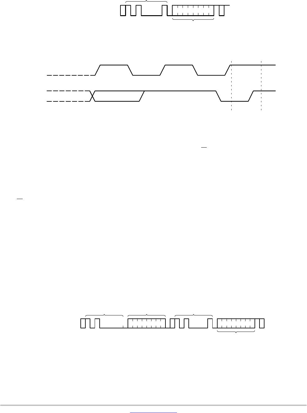
Figure 8. Byte Write Timing
BYTE
ADDRESS
SLAVE
ADDRESS
S
A
C
K
A
C
K
DATA
A
C
K
S
T
O
P
P
BUS ACTIVITY:
MASTER
SDA LINE
S
T
A
R
T
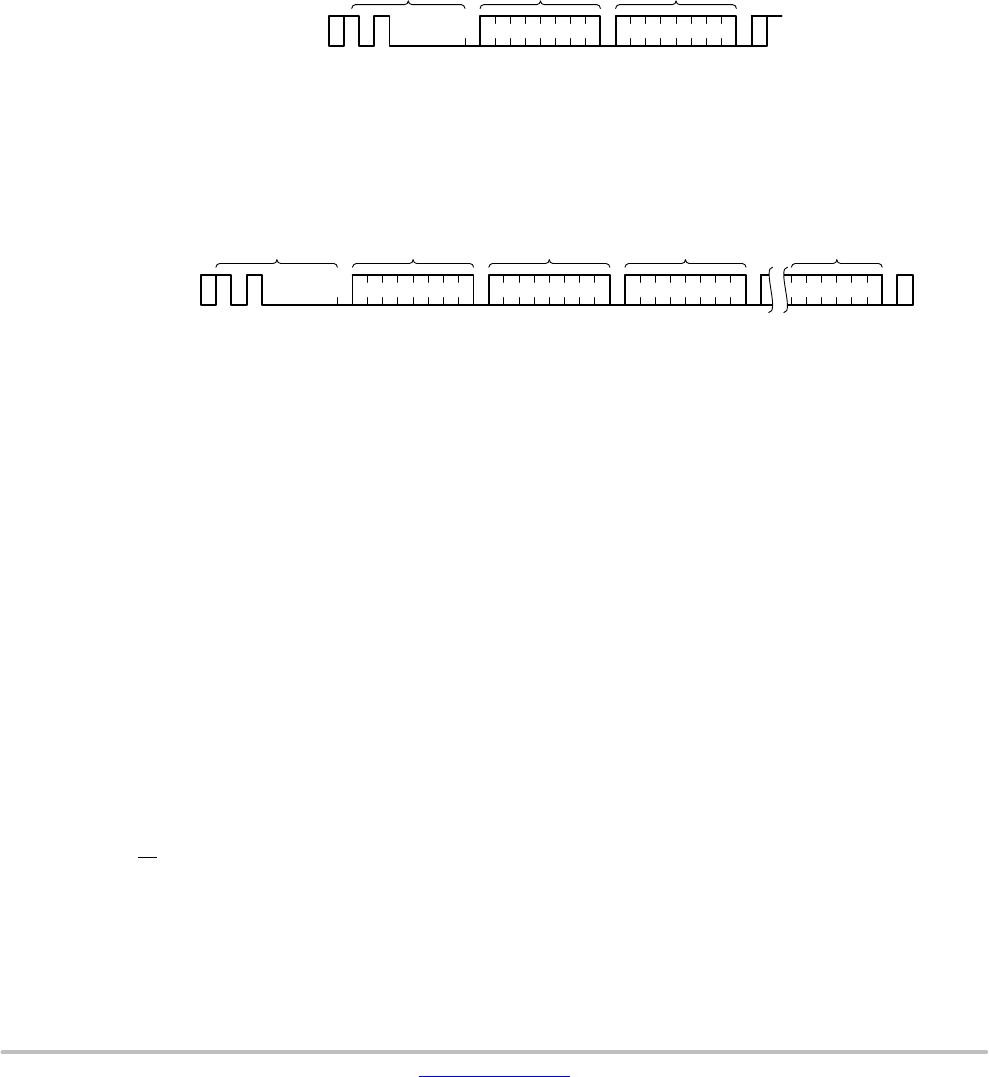
Figure 9. Page Write Timing
BUS ACTIVITY:
MASTER
SDA LINE
DATA n+15
BYTE
ADDRESS (n)
A
C
K
A
C
K
DATA n
A
C
K
S
T
O
P
S
A
C
K
DATA n+1
A
C
K
S
T
A
R
T
P
SLAVE
ADDRESS
Acknowledge Polling
Disabling of the inputs can be used to take advantage of
the typical write cycle time. Once the stop condition is issued
to indicate the end of the host’s write opration, the
CAT1021/22/23 initiates the internal write cycle. ACK
polling can be initiated immediately. This involves issuing
the start condition followed by the slave address for a write
operation. If the device is still busy with the write operation,
no ACK will be returned. If a write operation has completed,
an ACK will be returned and the host can then proceed with
the next read or write operation.
WRITE PROTECTION PIN (WP)
The Write Protection feature (CAT1021 only) allows the
user to protect against inadvertent memory array
programming. If the WP pin is tied to V
CC, the entire
memory array is protected and becomes read only. The
CAT1021 will accept both slave and byte addresses, but the
memory location accessed is protected from programming
by the device’s failure to send an acknowledge after the first
byte of data is received.
READ OPERATIONS
The READ operation for the CAT1021/22/23 is initiated
in the same manner as the write operation with one
exception, the R/W
bit is set to one. Three different READ
operations are possible: Immediate/Current Address
READ, Selective/Random READ and Sequential READ.
CAT1021, CAT1022, CAT1023
www.onsemi.com
12
Figure 10. Immediate Address Read Timing
SCL
SDA8TH BIT
STOPNO ACKDATA OUT
8
SLAVE
ADDRESS
S
A
C
K
DATA
N
O
A
C
K
S
T
O
P
P
BUS ACTIVITY:
MASTER
SDA LINE
S
T
A
R
T
9
Immediate/Current Address Read
The CAT1021/22/23 address counter contains the address
of the last byte accessed, incremented by one. In other
words, if the last READ or WRITE access was to address N,
the READ immediately following would access data from
address N + 1. For N = E = 255, the counter will wrap around
to zero and continue to clock out valid data. After the
CAT1021/22/23 receives its slave address information (with
the R/W
bit set to one), it issues an acknowledge, then
transmits the 8bit byte requested. The master device does
not send an acknowledge, but will generate a STOP
condition.
Selective/Random Read
Selective/Random READ operations allow the Master
device to select at random any memory location for a READ
operation. The Master device first performs a ‘dummy’
write operation by sending the START condition, slave
address and byte addresses of the location it wishes to read.
After the CAT1021/22/23 acknowledges, the Master device
sends the START condition and the slave address again, this
time with the R/W
bit set to one. The CAT1021/22/23 then
responds with its acknowledge and sends the 8bit byte
requested. The master device does not send an acknowledge
but will generate a STOP condition.
Sequential Read
The Sequential READ operation can be initiated by either
the Immediate Address READ or Selective READ
operations. After the CAT1021/22/23 sends the inital 8 bit
byte requested, the Master will responds with an
acknowledge which tells the device it requires more data.
The CAT1021/22/23 will continue to output an 8 bit byte
for each acknowledge, thus sending the STOP condition.
The data being transmitted from the CAT1021/22/23 is
sent sequentially with the data from address N followed by
data from address N + 1. The READ operation address
counter increments all of the CAT1021/22/23 address bits so
that the entire memory array can be read during one
operation.
Figure 11. Selective Read Timing
SLAVE
ADDRESS
S
A
C
K
N
O
A
C
K
S
T
O
P
P
BUS ACTIVITY:
MASTER
SDA LINE
S
T
A
R
T
BYTE
ADDRESS (n)
S
A
C
K
DATA n
SLAVE
ADDRESS
A
C
K
S
T
A
R
T

CAT1022YI-45-GT3

Mfr. #:
Manufacturer:
ON Semiconductor
Description:
Supervisory Circuits CPU SUP W/2K EEPROM
Lifecycle:
New from this manufacturer.
Delivery:
DHL FedEx Ups TNT EMS
Payment:
T/T Paypal Visa MoneyGram Western Union