LTC1727/LTC1728
4
17278fd
For more information www.linear.com/LTC1727
ELECTRICAL CHARACTERISTICS
LTC1728-3.3 The l denotes specifications which apply over the full operating temperature range, otherwise specifications are at
T
A
= 25°C. V
CC3
= 3.3V, V
CC18
= 1.8V, V
CCA
= V
CC3
unless otherwise noted.
Note 1: Stresses beyond those listed under Absolute Maximum Ratings
may cause permanent damage to the device. Exposure to any Absolute
Maximum Rating condition for extended periods may affect device
reliability and lifetime.
Note 2: All voltage values are with respect to GND.
Note 3: The LTC1727E/LTC1728E are guaranteed to meet specified
performance from 0°C to 70°C and are designed, characterized and
assured to meet the extended temperature limits of –40°C to 85°C
but are not tested at these temperatures.
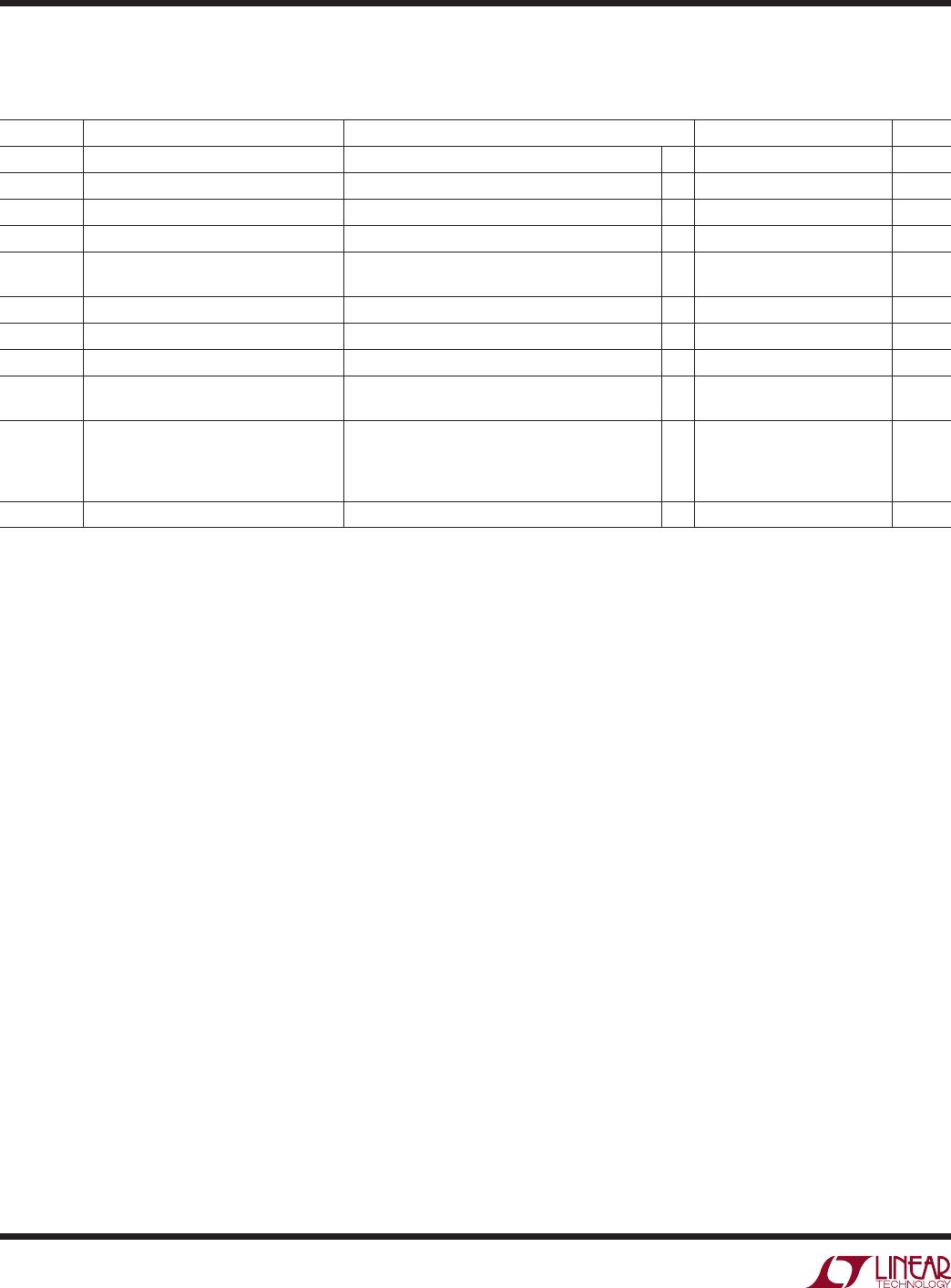
SYMBOL PARAMETER CONDITIONS MIN TYP MAX UNITS
V
RT3
Reset Threshold V
CC3
V
CC3
Input Threshold
l
3.036 3.086 3.135 V
V
RT18
Reset Threshold V
CC18
V
CC18
Input Threshold
l
1.656 1.683 1.710 V
V
RTA
Reset Threshold V
CCA
V
CCA
Input Threshold
l
0.985 1.000 1.015 V
V
CCOP
V
CC3
, V
CC18
Operating Voltage RST in Correct Logic State
l
1 7 V
I
VCC3
V
CC3
Supply Current V
CC18
> V
CC3
V
CC18
< V
CC3
, V
CC3
= 3.3V (Note 4)
l
l
1
10
2
20
µA
µA
I
VCC18
V
CC18
Supply Current V
CC18
< V
CC3
, V
CC18
= 1.8V (Note 4)
l
1 2 µA
I
VCCA
V
CCA
Input Current V
CCA
= 1V
l
–15 0 15 nA
t
RST
Reset Pulse Width RST Low (Note 5)
l
140 200 280 ms
t
UV
V
CC
Undervoltage Detect to RST V
CC18
, V
CC3
or V
CCA
Less Than Reset (Note 5)
Threshold V
RT
by More Than 1%
110 µs
V
OL
Output Voltage Low, RST I
SINK
= 2.5mA, V
CC3
= 3.3V, V
CC18
= 0V
I
SINK
= 100µA, V
CC3
= 1V, V
CC18
= 0V
I
SINK
= 100µA, V
CC3
= 0V, V
CC18
= 1V
I
SINK
= 100µA, V
CC3
= 1V, V
CC18
= 1V
l
l
l
l
0.15
0.05
0.05
0.05
0.4
0.3
0.3
0.3
V
V
V
V
V
OH
Output Voltage High, RST I
SOURCE
= 1µA (Note 6)
l
V
CC3
– 1 V
Note 4: Both V
CC3
and V
CC5
/V
CC25
/V
CC18
can act as the supply depending
on which pin has the greatest potential.
Note 5: Measured from when input passes through the input threshold
(V
RTX
) until RST or COMPX passes through 1.5V.
Note 6: The output pins RST and COMPX have internal pull-ups to V
CC3
of
typically 6µA. However, external pull-up resistors may be used when faster
rise times are required or for V
OH
voltages greater than V
CC3
.
Note 7: The V
CC5
reset override voltage is valid for an operating range less
than approximately 4.15V. Above this point the override is turned off and
the V
CC5
pin functions normally.