DATA SHEET • AA103-72/-72LF 1-BIT DIGITAL ATTENUATOR
Skyworks Solutions, Inc. • Phone [781] 376-3000 • Fax [781] 376-3100 • sales@skyworksinc.com • www.skyworksinc.com
2 February 24, 2011 • Skyworks Proprietary Information • Products and Product Information are Subject to Change Without Notice • 200199C
Table 1. AA103-72/-72LF Signal Descriptions
Pin # Name Description Pin # Name Description
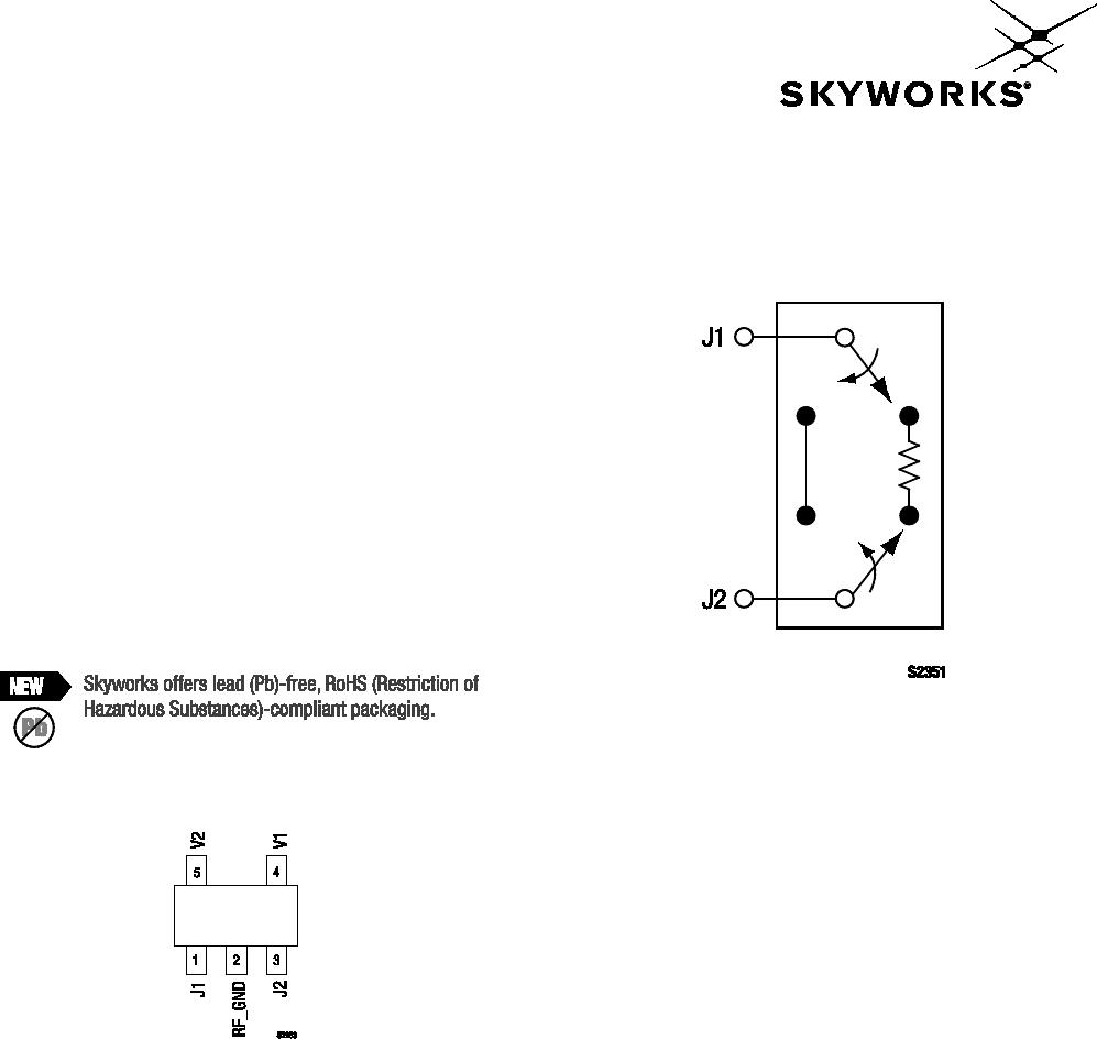
1 J1 RF port. Must be DC blocked. 4 V1 DC control bias
2 RF_GND RF ground. Must be AC-coupled to ground. 5 V2 DC control bias
3 J2 RF port. Must be DC blocked.
Table 2. AA103-72/-72LF Absolute Maximum Ratings
Parameter Symbol Minimum Maximum Units
RF input power PIN 1 W > 500 MHz 0/8 V
0.5 W @ 50 MHz 0/8 V
dBm
dBm
Supply voltage VS 8 V
Control voltage VCTL –0.2 +8.0 V
Operating temperature TOP –40 +85 °C
Storage temperature TSTG –65 +150 °C
Note: Exposure to maximum rating conditions for extended periods may reduce device reliability. There is no damage to device with only one parameter set at the limit and all other
parameters set at or below their nominal value. Exceeding any of the limits listed here may result in permanent damage to the device.
CAUTION: Although this device is designed to be as robust as possible, Electrostatic Discharge (ESD) can damage this device. This device
must be protected at all times from ESD. Static charges may easily produce potentials of several kilovolts on the human body
or equipment, which can discharge without detection. Industry-standard ESD precautions should be used at all times.
Electrical and Mechanical Specifications
The absolute maximum ratings of the AA103-72/-72LF are
provided in Table 2. Electrical specifications are provided in
Tables 3.
Typical performance characteristics of the AA103-72/-72LF are
illustrated in Figures 3 through 5.
The state of the AA103-72/-72LF is determined by the logic
provided in Table 4.