MKP479
www.vishay.com
Vishay BCcomponents
Revision: 23-Nov-15
1
Document Number: 28123
For technical questions, contact: dc-film@vishay.com
THIS DOCUMENT IS SUBJECT TO CHANGE WITHOUT NOTICE. THE PRODUCTS DESCRIBED HEREIN AND THIS DOCUMENT
ARE SUBJECT TO SPECIFIC DISCLAIMERS, SET FORTH AT www.vishay.com/doc?91000
AC and Pulse Polypropylene
Film Capacitors MKP Radial Epoxy Lacquered Type
APPLICATIONS
Low losses due to low contact resistance and low loss
dielectric result in applications where high currents at high
frequency occur or high stability is preferred. Their small
dimensions make them suitable for circuits with high
packaging density.
MARKING
Manufacturer’s emblem; C-value; tolerance; rated voltage;
manufacturer’s type designation; code for dielectric material
DIELECTRIC
Polypropylene film
ELECTRODES
Metallized
COATING
Flame retardant epoxy material (UL-class 94 V-0)
LEADS
Tinned wire
FEATURES
7.5 mm bent back pitch
10 mm to 27.5 mm lead pitch
Low contact resistance
Low loss dielectric
Supplied loose in box (including lock lead
versions) and taped on reel
Material categorization: for definitions of compliance
please see www.vishay.com/doc?99912
CONSTRUCTION
Wound mono construction
CAPACITANCE RANGE (E24 SERIES)
0.01 μF to 3.9 μF
CAPACITANCE TOLERANCE
± 5 %
RATED (DC) VOLTAGE
160 V; 250 V; 400 V; 630 V
RATED (AC) VOLTAGE
100 V; 160 V; 200 V
RATED PEAK-TO-PEAK VOLTAGE
280 V; 450 V; 560 V
CLIMATIC CATEGORY
55/105/56
RATED TEMPERATURE
85 °C
MAXIMUM APPLICATION TEMPERATURE
105 °C
REFERENCE SPECIFICATIONS
IEC 60384-17
PERFORMANCE GRADE
Grade 1 (long life)
STABILITY GRADE
Grade 2
DETAIL SPECIFICATION
For more detailed data and test requirements contact:
dc-film@vishay.com
seating
plane (1)
α∞
(2)
P
Ød
t
w
l
h
l
t
A
w
h'
l
F'
F
(3)
10
Ød
t
H
15
Dimensions in mm
Hole Ø 1.0 for d
t
= 0.6 mm
Hole Ø 1.3 for d
t
= 0.8 mm
0 ≤ α < 50°
|F - F’| < 0.3 mm
F = 7.5 mm + 0.6 mm / - 0.1 mm
A = 2.0 mm + 1.0 mm / - 0.5 mm (pitch = 10.0 mm)
A = 2.5 mm + 1.4 mm / - 0.5 mm (pitch = 15.0 mm; 22.5 mm and 27.5 mm)
l
t
h
l w
Ød
t
> 0.5
1.6
double
conical
hole
P
A A
magnified view
direction A
β
ϒ
β
ϒ
β ≤ 15
Dimensions in mm
MKP479
www.vishay.com
Vishay BCcomponents
Revision: 23-Nov-15
2
Document Number: 28123
For technical questions, contact: dc-film@vishay.com
THIS DOCUMENT IS SUBJECT TO CHANGE WITHOUT NOTICE. THE PRODUCTS DESCRIBED HEREIN AND THIS DOCUMENT
ARE SUBJECT TO SPECIFIC DISCLAIMERS, SET FORTH AT www.vishay.com/doc?91000
COMPOSITION OF CATALOG NUMBER
Notes
(1)
Small reel diameter = 356 mm is available on request
For detailed tape specifications refer to packaging information www.vishay.com/doc?28139
BFC2 479 XX XX X
2222 (*) 479 XX
XX X
(*) old ordering number
TYPE PACKAGING LEAD CONFIGURATION
PREFERRED TYPES
C-TOL.
160 V 250 V 400 V 630 V
479
Loose in box
Lead length 5.0 mm ± 1.0 mm
± 5 %
32 42 52 62
Lock lead 4.0 mm + 1.0 mm / - 0.5 mm
90 90 90 90
Taped on reel
(bent back)
H = 16.0 mm, P
0
= 15.0 mm;
reel diameter = 500 mm
(1)
36 46 56 66
Dimensions of this code numbers stay
between brackets
ON REQUEST
479
Loose in box
Lead length 3.5 mm + 1.0 mm / - 0.5 mm
(pitch 10 mm and 15 mm)
± 5 %
34 44 54 64
Lead length 3.5 mm ± 0.5 mm
(pitch 22.5 mm and 27.5 mm)
Taped on reel
H = 16.0 mm, P
0
= 12.7 mm;
reel diameter = 500 mm
35 45 55 65
479
15.0 mm / 7.5 mm
10.0 mm
15.0 mm
22.5 mm
27.5 mm
MULTIPLIER
(nF)
0.1
2
1
3
10
4
100
5
CAPACITANCE
(numerically; but not for lock lead)
Example:
104 = 10 x 10 = 100 nF
TYPE AND PITCHES
MKP479
www.vishay.com
Vishay BCcomponents
Revision: 23-Nov-15
3
Document Number: 28123
For technical questions, contact: dc-film@vishay.com
THIS DOCUMENT IS SUBJECT TO CHANGE WITHOUT NOTICE. THE PRODUCTS DESCRIBED HEREIN AND THIS DOCUMENT
ARE SUBJECT TO SPECIFIC DISCLAIMERS, SET FORTH AT www.vishay.com/doc?91000
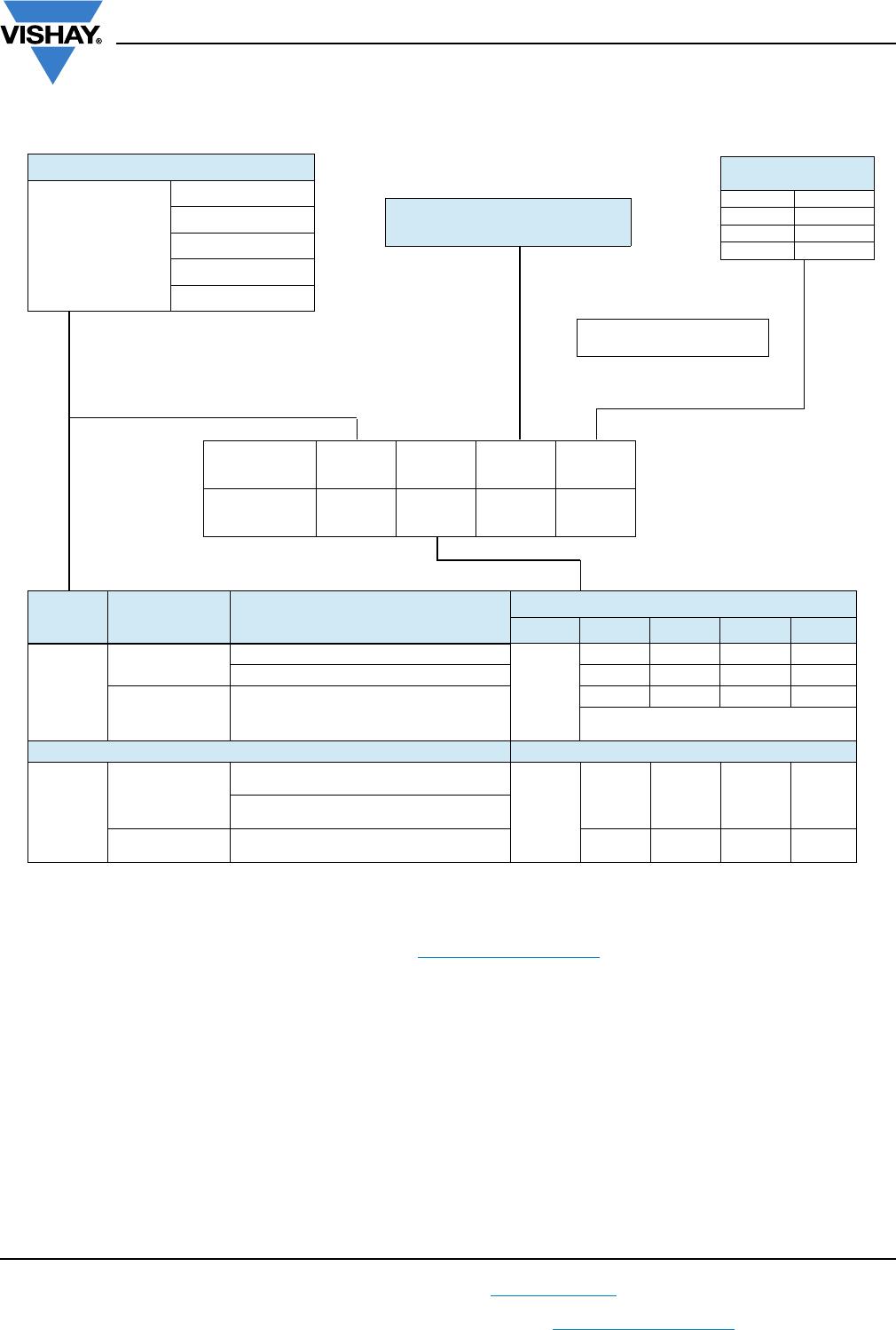
SPECIFIC REFERENCE DATA (160 V
DC
)
Note
(1)
See “Voltage Proof Test for Metalized Film Capacitors”: www.vishay.com/doc?28169
U
RDC
= 160 V; U
RAC
= 100 V; U
p-p
= 280 V (standard); C-tol. = ± 5 %
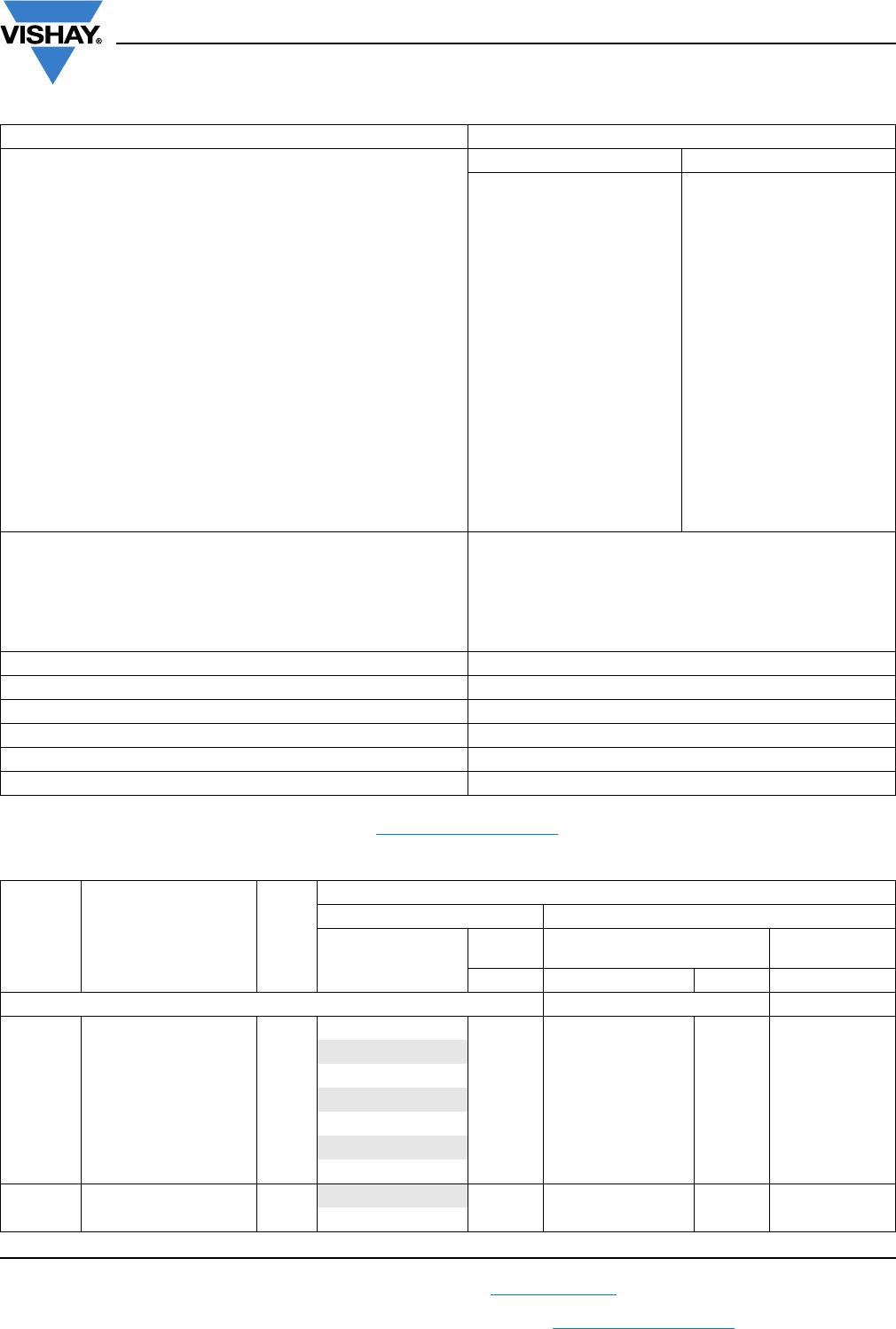
DESCRIPTION VALUE
Tangent of loss angle: at 10 kHz at 100 kHz
C = 0.075 μF 10 x 10
-4
25 x 10
-4
0.075 μF < C ≤ 0.11 μF 10 x 10
-4
30 x 10
-4
0.11 μF < C ≤ 0.18 μF 10 x 10
-4
35 x 10
-4
0.18 μF < C ≤ 0.3 μF 10 x 10
-4
40 x 10
-4
0.3 μF < C ≤ 0.47 μF 10 x 10
-4
60 x 10
-4
0.47 μF < C ≤ 0.82 μF 15 x 10
-4
90 x 10
-4
0.82 μF < C ≤ 1.1 μF 15 x 10
-4
100 x 10
-4
1.1 μF < C ≤ 1.2 μF 15 x 10
-4
120 x 10
-4
1.2 μF < C ≤ 1.3 μF 15 x 10
-4
125 x 10
-4
1.3 μF < C ≤ 1.8 μF 15 x 10
-4
135 x 10
-4
1.8 μF < C ≤ 2.4 μF 15 x 10
-4
145 x 10
-4
2.4 μF < C ≤ 3.0 μF 15 x 10
-4
155 x 10
-4
3.0 μF < C ≤ 3.3 μF 15 x 10
-4
165 x 10
-4
3.3 μF < C ≤ 3.6 μF 15 x 10
-4
175 x 10
-4
3.6 μF < C ≤ 3.9 μF 15 x 10
-4
185 x 10
-4
Rated voltage pulse slope (dU/dt)
R
at 160V
DC
:
P = 10mm 60V/μs
P = 15mm 50V/μs
P = 22.5mm 25V/μs
P = 27.5mm 15V/μs
R between leads, for C 1.0μF at 100V; 1min > 100 000M
RC between leads, for C > 1 μF at 100V; 1min > 100 000s
R between leads and case; 100V; 1min > 100 000M
Ionization (AC) voltage (typical value) at 50pC peak discharge > 220V
Withstanding (DC) voltage (cut off current 10mA); rise time 100V/s
(1)
256V; 1min
Withstanding (DC) voltage between leads and case 2840V; 1min
C
(μF)
DIMENSIONS
w
max.
x h (h’)
max.
x l
max.
(mm)
MASS
(g)
CATALOG NUMBER BFC2479..... AND PACKAGING
LOOSE IN BOX REEL
l
t
= 5.0 mm ± 1.0 mm
ALL
LEADS
PITCH 7.5 mm (BENT BACK)
ORIGINAL
PITCH
SPQ SPQ SPQ
Pitch = 10.0 mm ± 0.4mm; d
t
= 0.60 mm ± 0.06mm Pitch = 7.5mm (bent back) Pitch = 10.0mm
0.075
6.0 x 15.0 x 12.5 0.9
32753
1000 1000
0.082
32823
0.091 32913
0.10
32104
0.11 32114
0.12
32124
0.13 32134
0.15
6.5 x 15.5 x 12.5 1.0
32154
1000 900
0.16 32164

BFC247946474

Mfr. #:
Manufacturer:
Vishay
Description:
Film Capacitors .47uF 5% 250volts
Lifecycle:
New from this manufacturer.
Delivery:
DHL FedEx Ups TNT EMS
Payment:
T/T Paypal Visa MoneyGram Western Union