_______________General Description
The MAX4223–MAX4228 current-feedback amplifiers
combine ultra-high-speed performance, low distortion,
and excellent video specifications with low-power oper-
ation. The MAX4223/MAX4224/MAX4226/MAX4228
have a shutdown feature that reduces power-supply
current to 350µA and places the outputs into a high-
impedance state. These devices operate with dual sup-
plies ranging from ±2.85V to ±5.5V and provide a
typical output drive current of 80mA. The MAX4223/
MAX4225/MAX4226 are optimized for a closed-loop
gain of +1 (0dB) or more and have a -3dB bandwidth of
1GHz, while the MAX4224/MAX4227/MAX4228 are
compensated for a closed-loop gain of +2 (6dB) or
more, and have a -3dB bandwidth of 600MHz (1.2GHz
gain-bandwidth product).
The MAX4223–MAX4228 are ideal for professional video
applications, with differential gain and phase errors of
0.01% and 0.02°, 0.1dB gain flatness of 300MHz, and a
1100V/µs slew rate. Total harmonic distortion (THD) of
-60dBc (10MHz) and an 8ns settling time to 0.1% suit
these devices for driving high-speed analog-to-digital
inputs or for data-communications applications. The low-
power shutdown mode on the MAX4223/MAX4224/
MAX4226/MAX4228 makes them suitable for portable
and battery-powered applications. Their high output
impedance in shutdown mode is excellent for multiplex-
ing applications.
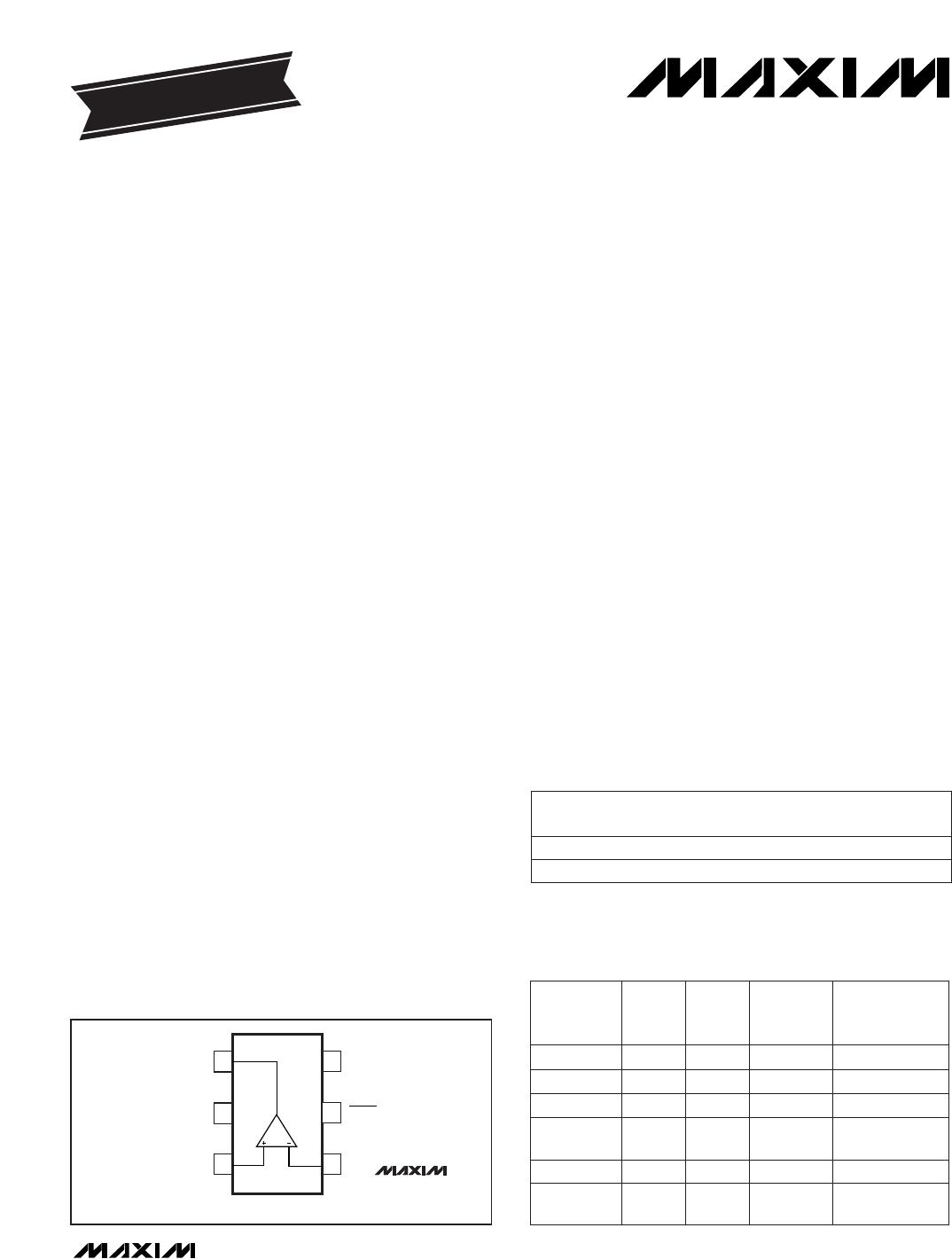
The single MAX4223/MAX4224 are available in space-
saving 6-pin SOT23 packages. All devices are available
in the extended -40°C to +85°C temperature range.
________________________Applications
ADC Input Buffers Data Communications
Video Cameras Video Line Drivers
Video Switches Video Multiplexing
Video Editors XDSL Drivers
RF Receivers Differential Line Drivers
____________________________Features
Ultra-High Speed and Fast Settling Time:
1GHz -3dB Bandwidth (MAX4223, Gain = +1)
600MHz -3dB Bandwidth (MAX4224, Gain = +2)
1700V/µs Slew Rate (MAX4224)
5ns Settling Time to 0.1% (MAX4224)
Excellent Video Specifications (MAX4223):
Gain Flatness of 0.1dB to 300MHz
0.01%/0.02° DG/DP Errors
Low Distortion:
-60dBc THD (f
c
= 10MHz)
42dBm Third-Order Intercept (f = 30MHz)
6.0mA Quiescent Supply Current (per amplifier)
Shutdown Mode:
350µA Supply Current (per amplifier)
100k Output Impedance
High Output Drive Capability:
80mA Output Current
Drives up to 4 Back-Terminated 75Loads to
±2.5V while Maintaining Excellent Differential
Gain/Phase Characteristics
Available in Tiny 6-Pin SOT23 and 10-Pin µMAX
Packages
MAX4223–MAX4228
1GHz, Low-Power, SOT23,
Current-Feedback Amplifiers with Shutdown
________________________________________________________________
Maxim Integrated Products
1
V
EE
IN-
IN+
1
6
V
CC
5
SHDN
OUT
MAX4223
MAX4224
SOT23-6
TOP VIEW
2
3
4
_________________Pin Configurations
19-1230; Rev 2a; 6/97
PART
MAX4223EUT-T
MAX4223ESA -40°C to +85°C
-40°C to +85°C
TEMP. RANGE
PIN-
PACKAGE
6 SOT23
8 SO
EVALUATION KIT
AVAILABLE
______________Ordering Information
_____________________Selector Guide
Pin Configurations
continued at end
of data sheet.
Ordering Information continued at end of data sheet.
For free samples & the latest literature: http://www.maxim-ic.com, or phone 1-800-998-8800
For small orders, phone 408-737-7600 ext. 3468.
SOT
TOP MARK
AAAD
10 µMAX,
14 SO
8 SO
10 µMAX,
14 SO
8 SO
6 SOT23, 8 SO
6 SOT23, 8 SO
PIN-
PACKAGE
Yes
No
Yes
No
Yes
Yes
SHUT-
DOWN
MODE
2
2
2
2
1
1
AMPS
PER
PKG.
2
2MAX4227
MAX4228
1
PART
1MAX4225
MAX4226
2
1MAX4223
MAX4224
MIN.
GAIN
MAX4223–MAX4228
1GHz, Low-Power, SOT23,
Current-Feedback Amplifiers with Shutdown
2 _______________________________________________________________________________________
ABSOLUTE MAXIMUM RATINGS
DC ELECTRICAL CHARACTERISTICS
(V
CC
= +5V, V
EE
= -5V, SHDN = 5V, V
CM
= 0V, R
L
= , T
A
= T
MIN
to T
MAX
, unless otherwise noted. Typical values are at
T
A
= +25°C.) (Note 1)
Stresses beyond those listed under “Absolute Maximum Ratings” may cause permanent damage to the device. These are stress ratings only, and functional
operation of the device at these or any other conditions beyond those indicated in the operational sections of the specifications is not implied. Exposure to
absolute maximum rating conditions for extended periods may affect device reliability.
Supply Voltage (V
CC
to V
EE
)..................................................12V
Analog Input Voltage .......................(V
EE
- 0.3V) to (V
CC
+ 0.3V)
Analog Input Current........................................................±25mA
SHDN Input Voltage.........................(V
EE
- 0.3V) to (V
CC
+ 0.3V)
Short-Circuit Duration
OUT to GND...........................................................Continuous
OUT to V
CC
or V
EE
............................................................5sec
Continuous Power Dissipation (T
A
= +70°C)
6-Pin SOT23 (derate 7.1mW/°C above +70°C).............571mW
8-Pin SO (derate 5.9mW/°C above +70°C)...................471mW
10-Pin µMAX (derate 5.6mW/°C above +70°C)............444mW
14-Pin SO (derate 8.3mW/°C above +70°C).................667mW
Operating Temperature Range ...........................-40°C to +85°C
Storage Temperature Range.............................-65°C to +150°C
Lead Temperature (soldering, 10sec).............................+300°C
CONDITIONS
±0.5 ±4
UNITSMIN TYP MAXSYMBOLPARAMETER
mV
±0.5 ±5
V
OS
Input Offset Voltage
±2 ±10
Input Bias Current
(Positive Input)
±7
T
A
= T
MIN
to T
MAX
µA
±15
T
A
= +25°C
45R
IN-
Input Resistance (Negative Input)
k700R
IN+
Input Resistance (Positive Input)
55 61
Inferred from CMRR test V±2.5 ±3.2V
CM
Input Common-Mode
Voltage Range
Inferred from PSRR test V±2.85 ±5.5V
CC
/V
EE
V
CM
= ±2.5V
Operating Supply Voltage
Range
68 74
dB
50
CMRRCommon-Mode Rejection Ratio
V
CC
= 2.85V to 5.5V,
V
EE
= -2.85V to -5.5V
dB
63
PSRRPower-Supply Rejection Ratio
Shutdown mode (SHDN = 0V)
mA
0.35 0.55
R
L
= 50
I
SY
Quiescent Supply Current
(per Amplifier)
Normal mode (SHDN = 5V)
6.0 9.0
V±2.5 ±2.8V
OUT
Output Voltage Swing
V
OUT
= ±2.5V M
0.3 0.8
T
R
Open-Loop Transresistance
V
OUT
= ±2.5V mA60 80I
OUT
Output Current (Note 2)
0.7 1.5
R
L
= short to ground mA140I
SC
Short-Circuit Output Current
V0.8V
IL
SHDN Logic Low
±4 ±20
T
A
= +25°C
µA
±4 ±25
I
B+
T
A
= +25°C
T
A
= T
MIN
to T
MAX
T
A
= +25°C
T
A
= T
MIN
to T
MAX
R
L
=
R
L
= 50
V2.0V
IH
SHDN Logic High
±6
T
A
= T
MIN
to T
MAX
MAX4223/MAX4224
MAX4223/MAX4224
MAX4225–MAX4228
µV/°C±2TCV
OS
Input Offset Voltage Drift
MAX4225–MAX4228
T
A
= T
MIN
to T
MAX
±30
Input Bias Current
(Negative Input)
±35
I
B-
T
A
= +25°C
MAX4223/MAX4224
MAX4225–MAX4228
MAX4223/MAX4224
MAX4225–MAX4228
MAX4223–MAX4228
1GHz, Low-Power, SOT23,
Current-Feedback Amplifiers with Shutdown
_______________________________________________________________________________________ 3
DC ELECTRICAL CHARACTERISTICS (continued)
(V
CC
= +5V, V
EE
= -5V, SHDN = 5V, V
CM
= 0V, R
L
= , T
A
= T
MIN
to T
MAX
, unless otherwise noted. Typical values are at
T
A
= +25°C.) (Note 1)
AC ELECTRICAL CHARACTERISTICS
(V
CC
= +5V, V
EE
= -5V, SHDN = 5V, V
CM
= 0V, A
V
= +1V/V for MAX4223/MAX4225/MAX4226, A
V
= +2V/V for MAX4224/MAX4227/
MAX4228, R
L
= 100, T
A
= +25°C, unless otherwise noted.) (Note 4)
10 100
CONDITIONS
25 70
UNITSMIN TYP MAXSYMBOLPARAMETER
µAI
IL
/I
IH
SHDN Input Current SHDN = 0V or 5V
SHDN = 0V, V
OUT
= -2.5V to +2.5V
(Note 3)
Shutdown Mode Output
Impedance
k
MAX4224/7/8
MAX4223/5/6
60 200
100 300
MAX4223/5/6
0.1
V
OUT
= 2V step
MAX4224/7/8
THD
850 1100
1.5
Total Harmonic Distortion
R
L
= 1k
1400 1700
250
-65
V
OUT
= 4V step
625 800
dB
CONDITIONS
Gain Peaking
V
OUT
= 2Vp-p MHz
330
BW
LS
Large-Signal Bandwidth
MAX4223/4/6/8
V
OUT
= 2V step
R
L
= 100
MAX4223/5/6
MAX4223/5/6
µs2
0.02
t
ON
Turn-On Time from Shutdown
SHDN = 0V, f = 10MHz, MAX4223/4/6/8
dB65Off Isolation
R
L
= 150(Note 6)
0.01
degrees
0.01
V
CC
, V
EE
= 0V to ±5V step ns100t
UP
MAX4223/4/6/8
Power-Up Time
R
L
= 150(Note 6) %
0.02
DGDifferential Gain Error
ns300t
OFF
Turn-Off Time to Shutdown
f = 30MHz,
R
S
= 50
MAX4225/6
-60
325 600
dBc
-61
MAX4223/5/6
750 1000
MAX4224/7/8
-78
MAX4224/7/8
DPDifferential Phase Error
MAX4224/7/8
MAX4224/7/8
MAX4223/5/6
MAX4223/5/6
Rising edge
MAX4223/5/6
V
OUT
= 2Vp-p,
f
C
= 10MHz
MAX4224/7/8
MAX4223/5/6
1.0
Falling edge
1100 1400
V/µsSRSlew Rate (Note 5)
MAX4224/7/8
1.5
UNITSMIN TYP MAXSYMBOLPARAMETER
ns
MAX4224/7/8
t
r
, t
f
Rise and Fall Time
MAX4223/5/6
MAX4223/5/6
MAX4224/7/8
MAX4223/5/6
V
OUT
= 20mVp-p MHz
MAX4224/7/8
BW
0.1dB
Bandwidth for ±0.1dB
Gain Flatness (Note 5)
V
OUT
= 20mVp-p
-72
MAX4227/8
-68
8
dB
ns
5
X
TALK
t
S
Settling Time to 0.1%
Crosstalk
MHzBW
-3dB Small-Signal Bandwidth
(Note 5)
MAX4224/7/8

MAX4224EUT+T

Mfr. #:
Manufacturer:
Maxim Integrated
Description:
High Speed Operational Amplifiers 1GHz Current Feedback Amp
Lifecycle:
New from this manufacturer.
Delivery:
DHL FedEx Ups TNT EMS
Payment:
T/T Paypal Visa MoneyGram Western Union