REV. A
AD8047/AD8048
–13–
R
F
R
L
1k
C
L
AD8047
R
SERIES
Figure 6. Driving Capacitive Loads
5ns
500mV
Figure 7. AD8047 Large Signal Transient Response;
V
O
= 2 V p-p, G = +1, R
F
= 0
, R
SERIES
= 0
, C
L
= 27 pF
R
F
R
IN
R
L
1k
C
L
AD8048
R
SERIES
Figure 8. Driving Capacitive Loads
5ns
500mV
Figure 9. AD8048 Large Signal Transient Response;
V
O
= 2 V p-p, G = +2, R
F
= R
IN
= 200
, R
SERIES
= 0
,
C
L
= 27 pF
APPLICATIONS
The AD8047 and AD8048 are voltage feedback amplifiers well
suited for such applications as photodetectors, active filters, and
log amplifiers. The devices’ wide bandwidth (260 MHz), phase
margin (65°), low noise current (1.0 pA/Hz), and slew rate
(1000 V/µs) give higher performance capabilities to these appli-
cations over previous voltage feedback designs.
With a settling time of 30 ns to 0.01% and 13 ns to 0.1%, the
devices are an excellent choice for DAC I/V conversion. The
same characteristics along with low harmonic distortion make
them a good choice for ADC buffering/amplification. With
superb linearity at relatively high signal frequencies, the AD8047
and AD8048 are ideal drivers for ADCs up to 12 bits.
Operation as a Video Line Driver
The AD8047 and AD8048 have been designed to offer out-
standing performance as video line drivers. The important
specifications of differential gain (0.01%) and differential phase
(0.02°) meet the most exacting HDTV demands for driving
video loads.
+V
S
–V
S
V
IN
V
OU
T
10F
10F
0.1F
0.1F
AD8047/
AD8048
3
2
7
6
4
75
75
75
75
CABLE
75
CABLE
200200
Figure 10. Video Line Driver
Active Filters
The wide bandwidth and low distortion of the AD8047 and
AD8048 are ideal for the realization of higher bandwidth active
filters. These characteristics, while being more common in many
current feedback op amps, are offered in the AD8047 and AD8048
in a voltage feedback configuration. Many active filter configu-
rations are not realizable with current feedback amplifiers.
A multiple feedback active filter requires a voltage feedback
amplifier and is more demanding of op amp performance than
other active filter configurations such as the Sallen-Key. In
general, the amplifier should have a bandwidth that is at least
10 times the bandwidth of the filter if problems due to phase
shift of the amplifier are to be avoided.
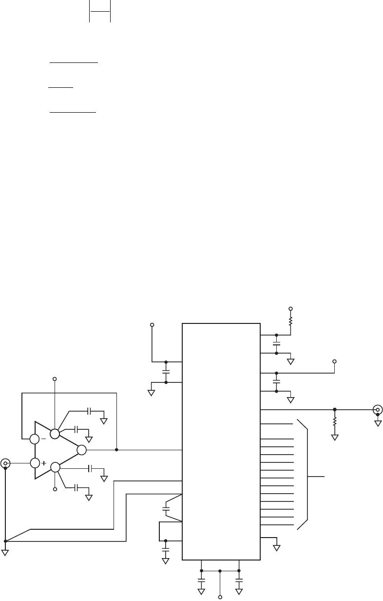
Figure 11 is an example of a 20 MHz low-pass multiple feed-
back active filter using an AD8048.
+5V
–5V
V
OUT
C1
50pF
C2
100pF
R3
78.7
R4
154
R1
154
10F
10F
0.1F
0.1F
AD8048
3
2
7
6
5
1
4
100
V
IN
Figure 11. Active Filter Circuit
It is worth noting that the frequency response of the circuit
when driving large capacitive loads will be dominated by the
passive roll-off of R
SERIES
and C
L
.
REV. A–14–
AD8047/AD8048
Choose
F
O
= Cutoff Frequency = 20 MHz
= Damping Ratio = 1/Q = 2
H = Absolute Value of Circuit Gain =
R4
R1
= 1
Then,
k = 2 π F
O
C1
C2 =
4 C1(H +1)
α
2
R1 =
α
2 HK
R3 =
α
2 K (H +1)
R4 = H(R1)
A/D Converter Driver
As A/D converters move toward higher speeds with higher reso-
lutions, there becomes a need for high performance drivers that
will not degrade the analog signal to the converter. It is desir-
able from a system’s standpoint that the A/D be the element in
the signal chain that ultimately limits overall distortion. This
places new demands on the amplifiers used to drive fast, high
resolution A/Ds.
With high bandwidth, low distortion, and fast settling time,
the AD8047 and AD8048 make high performance A/D drivers
for advanced converters. Figure 12 is an example of an AD8047
used as an input driver for an AD872A, a 12-bit, 10 MSPS
A/D converter.
MSB
BIT2
BIT3
BIT4
BIT5
BIT6
BIT7
BIT8
BIT9
BIT10
BIT11
BIT12
AV
DD
AGND
V
INA
REF GND
REF IN
REF OUT
AV
SS
AV
SS
AGND
OTR
CLK
DRGND
DRV
DD
DGND
DV
DD
19
18
17
16
15
14
13
12
11
10
9
8
24
25
3
26
28
27
1
20
21
23
22
6
7
4
5
V
INB
–5V ANALOG
AD872A
+5V ANALOG
ANALOG IN
DIGITAL OUTPUT
0.1F
0.1F
0.1F
0.1F
0.1F 0.1F
1F
10
49.9
CLOCK INPUT
+5V ANALOG
+5V DIGITAL
+5V DIGITAL
2
–5V
ANALOG
10F
10F
0.1F
0.1F
AD8047
3
2
7
6
4
Figure 12. AD8047 Used as Driver for an AD872A, a 12-Bit, 10 MSPS A/D Converter
Layout Considerations
The specified high speed performance of the AD8047 and
AD8048 requires careful attention to board layout and compo-
nent selection. Proper RF design techniques and low-pass
parasitic component selection are mandatory.
The PCB should have a ground plane covering all unused por-
tions of the component side of the board to provide a low
impedance path. The ground plane should be removed from the
area near the input pins to reduce stray capacitance.
Chip capacitors should be used for the supply bypassing (see
Figure 12). One end should be connected to the ground plane
and the other within 1/8 inch of each power pin. An additional
large (0.47 µF to 10 µF) tantalum electrolytic capacitor should
be connected in parallel, though not necessarily so close, to the
supply current for fast, large signal changes at the output.
The feedback resistor should be located close to the inverting
input pin in order to keep the stray capacitance at this node to a
minimum. Capacitance variations of less than 1 pF at the inverting
input will significantly affect high speed performance.
Stripline design techniques should be used for long signal traces
(greater than about 1 inch). These should be designed with a
characteristic impedance of 50 or 75 and be properly termi-
nated at each end.
REV. A
AD8047/AD8048
–15–
OUTLINE DIMENSIONS
8-Lead Plastic Dual In-Line Package [PDIP]
(N-8)
Dimensions shown in inches and (millimeters)
SEATING
PLANE
0.180
(4.57)
MAX
0.150 (3.81)
0.130 (3.30)
0.110 (2.79)
0.060 (1.52)
0.050 (1.27)
0.045 (1.14)
8
1
4
5
0.295 (7.49)
0.285 (7.24)
0.275 (6.98)
0.100 (2.54)
BSC
0.375 (9.53)
0.365 (9.27)
0.355 (9.02)
0.150 (3.81)
0.135 (3.43)
0.120 (3.05)
0.015 (0.38)
0.010 (0.25)
0.008 (0.20)
0.325 (8.26)
0.310 (7.87)
0.300 (7.62)
0.022 (0.56)
0.018 (0.46)
0.014 (0.36)
CONTROLLING DIMENSIONS ARE IN INCHES; MILLIMETER DIMENSIONS
(IN PARENTHESES) ARE ROUNDED-OFF INCH EQUIVALENTS FOR
REFERENCE ONLY AND ARE NOT APPROPRIATE FOR USE IN DESIGN
COMPLIANT TO JEDEC STANDARDS MO-095AA
0.015
(0.38)
MIN
8-Lead Standard Small Outline Package [SOIC]
(R-8)
Dimensions shown in millimeters and (inches)
0.25 (0.0098)
0.17 (0.0067)
1.27 (0.0500)
0.40 (0.0157)
0.50 (0.0196)
0.25 (0.0099)
45
8
0
1.75 (0.0688)
1.35 (0.0532)
SEATING
PLANE
0.25 (0.0098)
0.10 (0.0040)
85
41
5.00 (0.1968)
4.80 (0.1890)
4.00 (0.1574)
3.80 (0.1497)
1.27 (0.0500)
BSC
6.20 (0.2440)
5.80 (0.2284)
0.51 (0.0201)
0.31 (0.0122)
COPLANARITY
0.10
CONTROLLING DIMENSIONS ARE IN MILLIMETERS; INCH DIMENSIONS
(IN PARENTHESES) ARE ROUNDED-OFF MILLIMETER EQUIVALENTS FOR
REFERENCE ONLY AND ARE NOT APPROPRIATE FOR USE IN DESIGN
COMPLIANT TO JEDEC STANDARDS MS-012AA

AD8047ARZ-REEL7

Mfr. #:
Manufacturer:
Analog Devices Inc.
Description:
High Speed Operational Amplifiers 250MHz Gen Purp VTG Feedback
Lifecycle:
New from this manufacturer.
Delivery:
DHL FedEx Ups TNT EMS
Payment:
T/T Paypal Visa MoneyGram Western Union