15
FN8164.7
August 17, 2015
X9241A
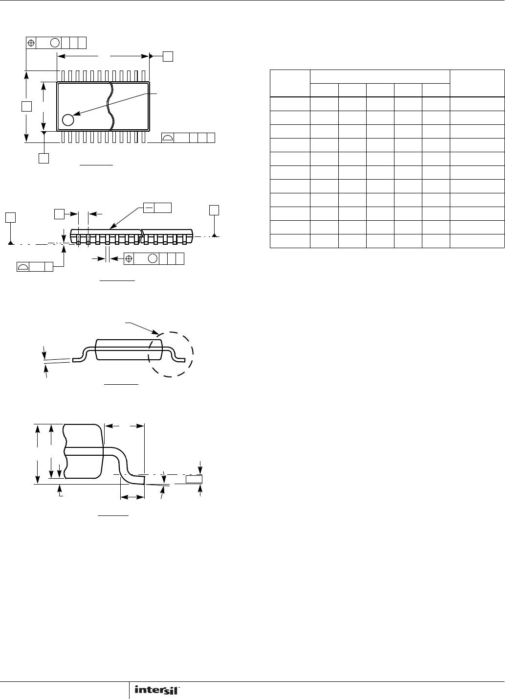
Thin Shrink Small Outline Package Family (TSSOP)
N
(N/2)+1
(N/2)
TOP VIEW
AD
0.20 C
2X
B A
N/2 LEAD TIPS
B
E1
E
0.25 CAB
M
1
H
PIN #1 I.D.
0.05
e
C
0.10 C
N LEADS
SIDE VIEW
0.10 CABM
b
c
SEE DETAIL “X”
END VIEW
DETAIL X
A2
0° - 8°
GAUGE
PLANE
0.25
L
A1
A
L1
SEATING
PLANE
MDP0044
THIN SHRINK SMALL OUTLINE PACKAGE FAMILY
SYMBOL
MILLIMETERS
TOLERANCE14 LD 16 LD 20 LD 24 LD 28 LD
A 1.20 1.20 1.20 1.20 1.20 Max
A1 0.10 0.10 0.10 0.10 0.10 ±0.05
A2 0.90 0.90 0.90 0.90 0.90 ±0.05
b 0.25 0.25 0.25 0.25 0.25 +0.05/-0.06
c 0.15 0.15 0.15 0.15 0.15 +0.05/-0.06
D 5.00 5.00 6.50 7.80 9.70 ±0.10
E 6.40 6.40 6.40 6.40 6.40 Basic
E1 4.40 4.40 4.40 4.40 4.40 ±0.10
e 0.65 0.65 0.65 0.65 0.65 Basic
L 0.60 0.60 0.60 0.60 0.60 ±0.15
L1 1.00 1.00 1.00 1.00 1.00 Reference
Rev. F 2/07
NOTES:
1. Dimension “D” does not include mold flash, protrusions or gate
burrs. Mold flash, protrusions or gate burrs shall not exceed
0.15mm per side.
2. Dimension “E1” does not include interlead flash or protrusions.
Interlead flash and protrusions shall not exceed 0.25mm per
side.
3. Dimensions “D” and “E1” are measured at dAtum Plane H.
4. Dimensioning and tolerancing per ASME Y14.5M-1994.