Silicon Bridge Rectifiers
Page 1
REV: C
KBPC10005W-G Thru. KBPC5010W-G Series
Parameter
Symbol
Unit
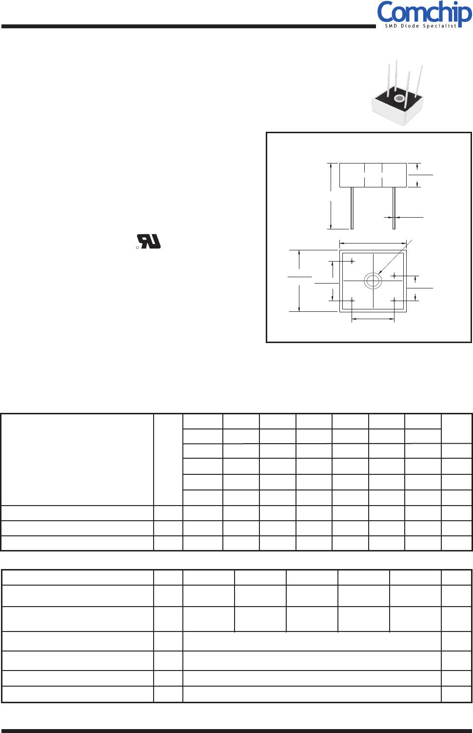
Dimensions in inches and (millimeter)
QW-BBR56
Maximum Recurrent Peak R Voltageeverse
Maximum Average Forward
Rectified Output Current @Tc=55°C
Peak Forward Surge Current ,
8.3ms Single Half Sine-Wave
Super Imposed On Rated Load
Operating Temperature Range
Storage Temperature Range
Reverse Voltage: 50 to 1000V
Forward Current: 10/15/25/35/50A
RoHS Device
Maximum ratings and electrical characteristics
Rating at 25°C ambient temperature unless otherwise specified.
Single phase, half wave ,60Hz, resistive or inductive load.
For capacitive load, derate current by 20%
KBPC_W-G
50
15005
25005
VRRM
I(AV)
IFSM
VF
IR
TJ
TSTG
1.1
10.0
-55 to +150
-55 to +150
V
V
V
A
A
V
μA
°C
KBPC-W
KBPC_W-G
100
1501
2501
KBPC_W-G
200
1504
2504
KBPC_W-G
400
1506
2506
KBPC_W-G
600
KBPC_W-G
800
1508
2508
KBPC_W-G
1000
1510
2510
Comchip Technology CO., LTD.
Features
-Surge overload -240~500 Amperes peak.
-Low forward voltage drop.
Mechanical Data
-Polarity: As marked on Body.
-Mounting position: Any.
10005 1001 1004 1006 1008 1010
Maximum Reverse Current at rate
DC Blocking Voltage Per Element @ TJ=25 °C
Maximum Forward Voltage Drop Per Element
at 5.0/7.5/12.5/17.5/25.0A Peak
-Electrically isolated base -2000 Volts.
35005
V
3501 3504 3506 3508 3510
50005
V
5001 5004 5006 5008 5010
1502
2502
1002
3502
5002
Maximum RMS Bridge Input Voltage
35
VRMS V
70 140 280 420 560 700
Parameter
KBPC10
Symbol
KBPC15 KBPC25
KBPC35
KBPC50
10 15 25
35
50
240
300
400 400 500
Unit
°C
Hole for
No.8 screw
193"(4.9)diam
0.442(11.23)
0.424(10.77)
0.042(1.07)
0.038(0.97)
1.133(28.80)
1.114(28.30)
0.469(11.90)
0.429(10.90)
0.732(18.60)
0.693(17.60)
0.732(18.60)
0.693(17.60)
1.133(28.80)
1.114(28.30)
1.20(30.5)min
-Weight: 25.95 grams (approx.).
-Materials used carries UL recognition.
Maximum DC Blocking Voltage
50
VDC V
100 200 400 600 800 1000
Company reserves the right to improve product design , functions and reliability without notice.
R
-UL recognized file # E349301

