Characteristics STPS10L60C
2/7 Doc ID 6426 Rev 5
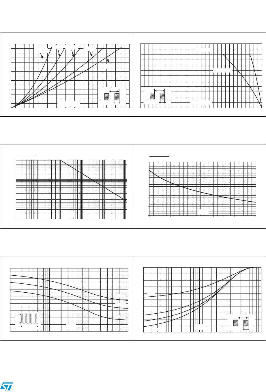
1 Characteristics
When the diodes 1 and 2 are used simultaneously :
ΔTj(diode 1) = P(diode1) x R
th(j-c)
(Per diode) + P(diode 2) x R
th(c)
To evaluate the conduction losses use the following equation:
P = 0.44 x I
F(AV)
+ 0.0091x I
F
2
(RMS)
Table 2. Absolute ratings (limiting values, per diode)
Symbol Parameter Value Unit
V
RRM
Repetitive peak reverse voltage 60 V
I
F(RMS)
Forward rms current 30 A
I
F(AV)
Average forward current
T
C
= 130 °C
δ = 0.5
Per diode
Per device
5
10
A
I
FSM
Surge non repetitive forward current tp = 10 ms Sinusoidal 180 A
I
RRM
Repetitive peak reverse current tp = 2 µs square F=1 kHz 1 A
P
ARM
Repetitive peak avalanche power
tp = 1 µs T
j
= 25 °C
4000 W
T
stg
Storage temperature range
-65 to +
175
°C
T
j
Maximum operating junction temperature
(1)
1. thermal runaway condition for a diode on its own heatsink
150 °C
dV/dt Critical rate of rise reverse voltage 10000 V/µs
Table 3. Thermal resistance
Symbol Parameter Value Unit
R
th (j-c)
Junction to case
Per diode
To ta l
4.5
3.5
° C/W
R
th (c)
Coupling 2.5 ° C/W
Table 4. Static electrical characteristics (per diode)
Symbol Parameter Tests Conditions Min. Typ. Max. Unit
I
R
(1)
1. Pulse test : tp = 380 µs, δ < 2%
Reverse leakage current
T
j
= 25 °C
V
R
= V
RRM
220
µA
T
j
= 125 °C
45 60
mA
V
F
(1)
Forward voltage drop
T
j
= 25 °C
I
F
= 5 A 0.55
V
T
j
= 125 °C
I
F
= 5 A 0.43 0.52
T
j
= 25 °C
I
F
= 10 A 0.67
T
j
= 125 °C
I
F
= 10 A 0.55 0.64
dPtot
dTj
---------------
1
Rth j a–()
--------------------------
<