Skyworks Solutions, Inc. • Phone [781] 376-3000 • Fax [781] 376-3100 • sales@skyworksinc.com • www.skyworksinc.com
202886B • Skyworks Proprietary Information • Products and Product Information are Subject to Change Without Notice • January 9, 2015 1
DATA SHEET
SKY65362-11: 900 to 930 MHz High-Power RF Front-End
Module
Applications
Smart meters
In-home appliances
Smart thermostats
Features
Integrated PA with +30.5 dBm output power
Integrated LNA with programmable bypass
Low FEM NF of 2.5 dB, typical
Single-ended 50 Ω transmit/receive RF interface
Supply voltage: 3.00 V to 5.25 V
Sleep mode current: <1 μA
Small MCM (36-pin, 6 x 6 mm) package
(MSL3, 260 C per JEDEC J-STD-020)
Skyworks Green
TM
products are compliant with
all applicable legislation and are halogen-free.
For additional information, refer to Skyworks
Definition of Green
TM
, document number
SQ04–0074.
Description
The SKY65362-11 is a high-performance, highly integrated RF
front-end module (FEM) designed for high-power Industrial,
Scientific, Medical (ISM) band applications operating in the 900 to
930 MHz frequency range.
The FEM is designed for ease of use and maximum flexibility with
fully matched, 50 Ω power amplifier (PA) input and output, and
digital controls compatible with 1.6 to 3.3 V CMOS levels.
The RF blocks operate over a wide supply voltage range from
3.00 to 5.25 V that allows the SKY65362-11 to be used in battery
powered applications over a wide spectrum of the battery
discharge curve.
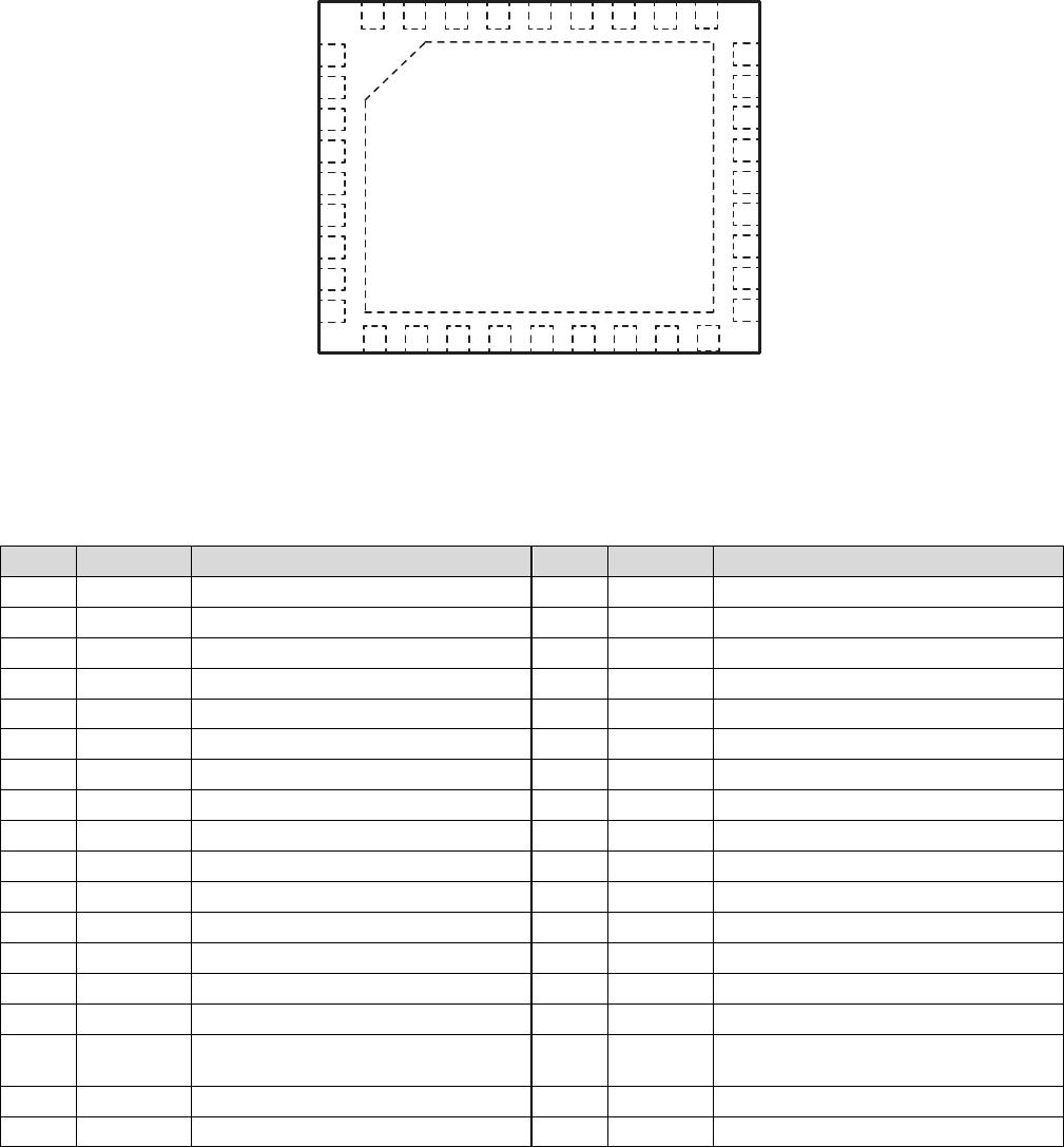
The SKY65362-11 is packaged in a 36-pin, 6 x 6 mm Multi-Chip
Module (MCM), which allows for a highly manufacturable low-cost
solution.
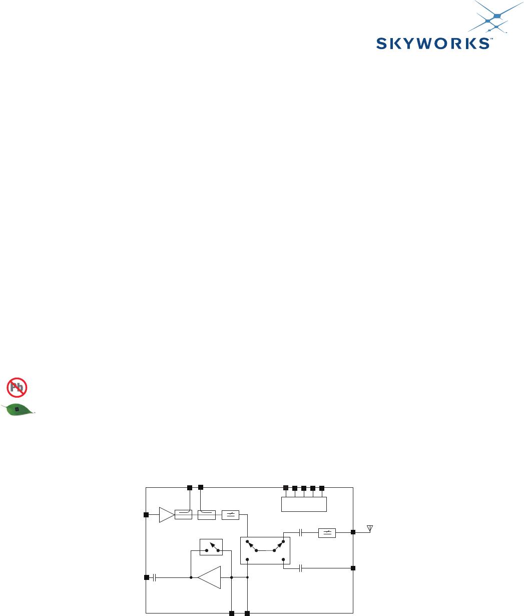
A functional block diagram of the SKY65362-11 is shown in
Figure 1. The 36-pin MCM package and pinout are shown in
Figure 2. Signal pin assignments and functional pin descriptions
are provided in Table 1.
Logic
control
Y0205
TX
TX
RX
RX
2-Stage
2-Stage
GaAs PA
GaAs PA
ANT1
ANT1
ANT2
ANT2
IALARM
IALARM
CTX
CTX
CSD
CSD
CPS
CPS
ANT_SEL
ANT_SEL
Switch
Switch
1-Stage
1-Stage
LNA
LNA
PDETF
PDETF
PDETR
PDETR
LNA_IN
LNA_IN
RX_FLT
RX_FLT
Figure 1. SKY65362-11 FEM Block Diagram
DATA SHEET • SKY65362-11: HIGH-POWER RF FEM
Skyworks Solutions, Inc. • Phone [781] 376-3000 • Fax [781] 376-3100 • sales@skyworksinc.com • www.skyworksinc.com
2 January 9, 2015 • Skyworks Proprietary Information • Products and Product Information are Subject to Change Without Notice • 202886B
1
2
3
4
5
6
7
8
9
10 11 12 13 14 15 16 17
18
36 35 34 33 32 31 30 29 28
19
20
21
22
23
24
25
26
27
GND
PA_IN
A
NT_SEL
PDETF
PDETR
CSD
CPS
CTX
IALARM
RX
GND
GND
GND
LNA_IN
GND
RX_FLT
GND
ANT_2
GND
VSUP1
VSUP2
VCC1
GND
VCC0
GND
VCC2
GND
GND
GND
GND
GND
GND
GND
GND
ANT_1
GND
Y0206
Figure 2. SKY65362-11 Pinout – 36-Pin MCM
(Top View)
Table 1. SKY65362-11 Signal Descriptions
Pin Name Description Pin Name Description
1 PA_IN PA input 19 GND Ground
2 GND Ground 20 ANT1 Antenna 1
3 PDETF Forward power detector output 21 GND Ground
4 PDETR Reverse power detector output 22 GND Ground
5 CSD Standby control (see Table 9) 23 GND Ground
6 CPS Receive mode gain control (see Table 9) 24 GND Ground
7 CTX Transmit/receive control (see Table 9) 25 GND Ground
8 IALARM PA current alarm output (see Table 9) 26 GND Ground
9 ANT_SEL Antenna select control input (see Table 9) 27 GND Ground
10 RX Receive output 28 GND Ground
11 GND Ground 29 VCC2 PA voltage supply
12 GND Ground 30 GND Ground
13 GND Ground 31 VCC0 Decoupling capacitor
14 LNA_IN LNA input 32 GND Ground
15 GND Ground 33 VCC1 PA voltage supply
16 RX_FLT Receive path after internal switches that connect
ANT1 and ANT2
34 VSUP2 FEM voltage supply
17 GND Ground 35 VSUP1 FEM voltage supply
18 ANT2 Antenna 2. No integrated filtering. 36 GND Ground
DATA SHEET • SKY65362-11: HIGH-POWER RF FEM
Skyworks Solutions, Inc. • Phone [781] 376-3000 • Fax [781] 376-3100 • sales@skyworksinc.com • www.skyworksinc.com
202886B • Skyworks Proprietary Information • Products and Product Information are Subject to Change Without Notice • January 9, 2015 3
Electrical and Mechanical Specifications
The absolute maximum ratings of the SKY65362-11 are provided
in Table 2. The recommended operating conditions are specified
in Table 3.
Electrical specifications are provided in Tables 4 through 8. The
state of the SKY65362-11 is determined by the logic provided in
Table 9.
Table 2. SKY65362-11 Absolute Maximum Ratings (Note 1)
Parameter Symbol Minimum Maximum Units
Supply voltage (no RF) VCC –0.3 +6.0 V
Control pin (CSD, CPS, CTX, IALARM, and ANT_SEL) voltage –0.3 VCC (VCC < 5 V) V
Operating temperature TA –40 +85 C
Storage temperature TSTG –40 +125 C
Transmit input power PIN_TX_MAX +10 dBm
Receive RF input power @ ANT1 or ANT2 ports PIN_RX_MAX +10 dBm
Voltage Standing Wave Ratio @ ANT1 or ANT2 ports VSWR 10:1
Electrostatic discharge:
Human Body Model (HBM), Class 1C
ESD
1000
V
Note 1: Exposure to maximum rating conditions for extended periods may reduce device reliability. There is no damage to device with only one parameter set at the limit and all other
parameters set at or below their nominal value. Exceeding any of the limits listed here may result in permanent damage to the device.
CAUTION: Although this device is designed to be as robust as possible, electrostatic discharge (ESD) can damage this device. This device
must be protected at all times from ESD. Static charges may easily produce potentials of several kilovolts on the human body
or equipment, which can discharge without detection. Industry-standard ESD precautions should be used at all times.
Table 3. SKY65362-11 Recommended Operating Conditions
Parameter Symbol Minimum Typical Maximum Units
Supply voltage VCC 4.75 5.00 5.25 V
Operating temperature TA –40 +25 +85 C

SKY65362-11

Mfr. #:
Manufacturer:
Skyworks Solutions, Inc.
Description:
RF Front End 900-930MHz NF 21.5dB Gain Tx/Rx 33/16dB
Lifecycle:
New from this manufacturer.
Delivery:
DHL FedEx Ups TNT EMS
Payment:
T/T Paypal Visa MoneyGram Western Union

Products related to this Datasheet