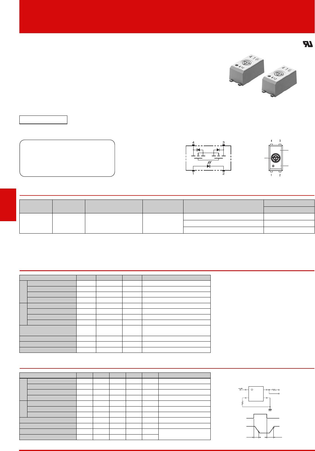
G3VM-41LR11-TR05

1
G3VM-41LR11
MOS FET Relays
World’s Smallest
*
SSOP Package MOS
FET Relays (C
OFF (typical): 0.7 pF, RON
(typical): 7 ) with Low Output
Capacitance and ON Resistance (C × R =
5 pF ) in a 40-V Load Voltage Model.
ON resistance of 7 (typical) suppresses output signal attenuation.
* As of March 2011 Survey by OMRON
Application Examples T
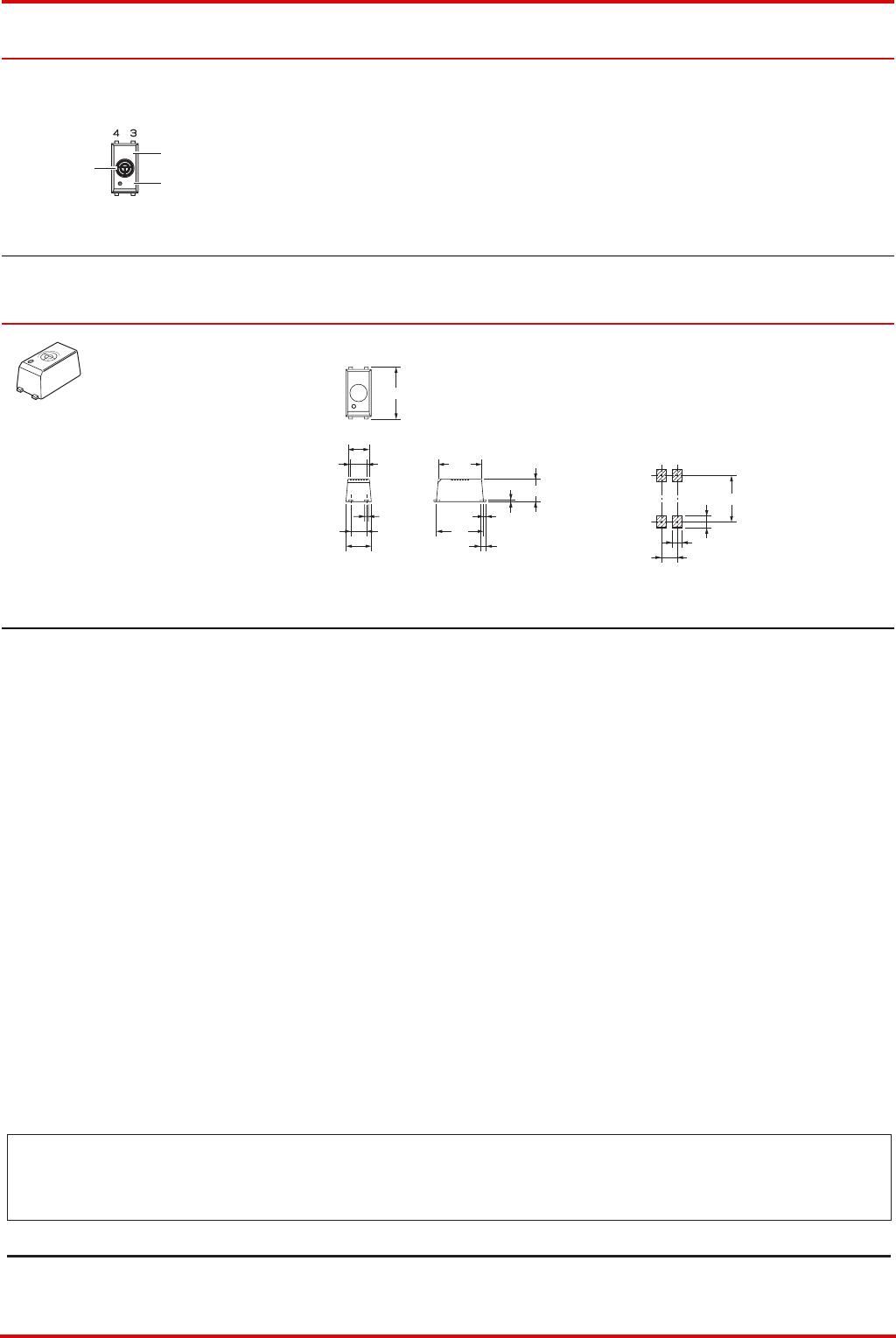
erminal Arrangement /Internal Connections
List of Models
Note: Ask your OMRON representative for orders under 1500 pcs or 500 pcs. We can supply products with the tape already cut.
Tape-cut SSOPs are packaged without humidity resistance. Use manual soldering to mount them.
Refer to common precautions.
* The AC peak and DC value are given for the load voltage.
Absolute Maximum Ratings (Ta = 25 °C)
Electrical Characteristics (Ta = 25 °C)
RoHS compliant
Note: The actual product is marked differently from the
image shown here.
Semiconductor test equipment
Test & Measurement equipment
Communication equipment
Data loggers
OMRON mark
Model name
LOT.No.
416
612
Note: The actual product is marked differently from the image shown here.
Package type Contact form Terminals
Load voltage
(peak value) *
Model
Minimum package quantity
Number per tape and reel
SSOP4
1a
(SPST-NO)
Surface-mounting Terminals 40 V
G3VM-41LR11 -
G3VM-41LR11 (TR05) 500
G3VM-41LR11 (TR) 1,500
Item Symbol Rating Unit Measurement conditions
Input
LED forward current IF 30 mA
Note: 1. The dielectric strength between the input and
output was checked by applying voltage
between all pins as a group on the LED side and
all pins as a group on the light-receiving side.
LED forward current reduction rate
IF/°C 0.3 mA/°C Ta 25 °C
LED reverse voltage VR 5 V
Connection temperature
TJ 125 °C
Output
Load voltage (AC peak/DC)
VOFF 40 V
Continuous load current (AC peak/DC)
IO 140 mA
ON current reduction rate
IO/°C 1.4 mA/°CTa 25 °C
Connection temperature
TJ 125 °C
Dielectric strength between
I/O (See note 1.)
V
I-O 1500 Vrms AC for 1 min
Ambient operating temperature
Ta 20 to +85 °C With no icing or condensation
Ambient storage temperature
Tstg 40 to +125 °C With no icing or condensation
Soldering temperature -260 °C10 s
Item Symbol
Minimum
Typical
Maximum
Unit Measurement conditions
Input
LED forward voltage VF 1.15 1.30 1.45 V IF = 5 mA
Note: 2. Turn-ON and Turn-OFF Times
Reverse current IR - - 10 µA VR = 5 V
Capacity between terminals
CT - 70 - pF V = 0, f = 1 MHz
Trigger LED forward current
IFT --3mA IO = 100 mA
Output
Maximum resistance with output ON
RON - 7 10
I
F
= 5 mA, I
O
= 140 mA, t < 1 s
Current leakage when the relay is open
ILEAK - 10 200 pA VOFF = 35 V, Ta = 25 °C
Capacity between terminals
COFF - 0.7 1.3 pF V = 0, f = 100 MHz, t < 1 s
Capacity between I/O terminals
CI-O - 0.3 - pF f = 1 MHz, VS = 0 V
Insulation resistance between I/O terminals
RI-O 1000 - - M
V
I-O
= 500 VDC, R
O
H
60 %
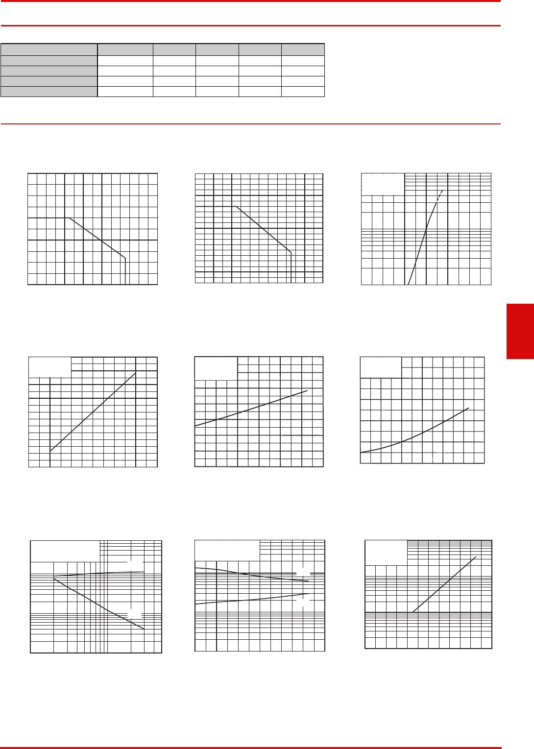
Turn-ON time tON - - 0.2 ms
I
F = 5 mA, RL = 200 ,
V
DD = 10 V (See note 2.)
Turn-OFF time tOFF - - 0.2 ms
VOUT
IF
tON tOFF
10%
90%
IF
1
2
4
3
RL
VDD
VOUT
2
G3VM-41LR11 MOS FET Relays
Recommended Operating Conditions
Use the G3VM under the following conditions so that the Relay will operate properly.
Engineering Data
Safety Precautions
Refer to "Common Precautions" for all G3VM models.
Item Symbol Minimum Typical Maximum Unit
Load voltage (AC peak/DC) VDD -- 32V
Operating LED forward current
IF --20mA
Continuous load current (AC peak/DC)
IO --140mA
Ambient operating temperature
Ta 25 - 60 °C
LED forward current vs. Ambient
temperature
Continuous load current vs. Ambient
temperature
LED forward current vs. LED forward
voltage
Continuous load current vs. On-state
voltage
On-state resistance vs. Ambient
temperature
Trigger LED forward current vs.
Ambient temperature
Turn ON, Turn OFF time vs. LED
forward current
Turn ON, Turn OFF time vs. Ambient
temperature
Current leakage vs. Ambient
temperature
I
F
- Ta
Ambient temperature Ta (°C)
LED forward current I
F
(mA)
0
10
20
30
40
50
-20 120 100 80 60 4020 0
I
O
- Ta
Ambient temperature Ta (°C)
Continuous load current I
O
(mA)
0
20
40
60
80
100
120
140
160
180
200
-20 120 100 80 60 40 20 0
I
F
- V
F
LED forward voltage V
F
(V)
LED forward current I
F
(mA)
1 1.1 1.2 1.3 1.4 1.5 1.6
3
5
30
50
1
10
100
Ta = 25 °C
I
O
- V
ON
On-state voltage V
ON
(V)
Continuous load current I
O
(mA)
Ta = 25 °C
I
F = 5 mA
-1.5
-1.0
-0.5 0 0.5 1.0 1.5
-200
-150
-100
-50
0
50
100
150
200
R
ON
- Ta
Ambient temperature Ta (°C)
On-state resistance R
ON
()
-200 20406080100
IO = 140 mA
I
F = 5 mA
t < 1 s
0
2
4
6
8
10
12
14
0
2
4
6
8
10
12
14
I
FT
- Ta
Ambient temperature Ta (°C)
Trigger LED forward current I
FT
(mA)
-20 0 20 40 60 80 100
IO = 140 mA
0
1
2
3
4
5
0
1
2
3
4
5
t
ON
, t
OFF
- I
F
LED forward current I
F
(mA)
Turn ON, Turn OFF time t
ON
, t
OFF
(µs)
3 5 30 50110
3
5
30
50
200
1
10
100
t
OFF
t
ON
Ta = 25 °C
V
DD = 10 V, RL = 200
t
ON
, t
OFF
- Ta
Ambient temperature Ta (°C)
Turn ON, Turn OFF time t
ON
, t
OFF
(µs)
3
5
30
50
1
10
100
-20 0 20 40 60 80 100
tOFF
tON
VDD = 10 V, RL = 200
I
F = 5 mA
I
LEAK
- Ta
Ambient temperature Ta (°C)
Current leakage I
LEAK
(pA)
VOFF = 35 V
1
10
100
1000
-20 0 20 40 60 80 100
Appearance/Dimensions SSOP4 type
Appearance
Dimensions (Unit: mm)
Note: The actual product is marked differently from the image shown here.
Actual Mounting Pad
Dimensions
(Recommended Value, TOP VIEW)
SSOP (Shrink Small Outline Package)
SSOP4
Note: The actual product is marked differently from the image shown here.
416
612
OMRON mark
Model name
LOT.No.
6
1
2
416
1.9
1.4 dia.
4.2
2.04
1.27
0.15
1.8
3.65
0.2
(0.46)
3.8
(0.3)
Unless otherwise specified, the
dimensional tolerance is ± 0.1 mm.
Surface-mounting Terminals
Weight: 0.03 g
3.73
0.95
0.8
1.27
Application examples provided in this document are for reference only. In actual applications, confirm equipment functions and safety before using the product.
Consult your OMRON representative before using the product under conditions which are not described in the manual or applying the product to nuclear control systems, railroad
systems, aviation systems, vehicles, combustion systems, medical equipment, amusement machines, safety equipment, and other systems or equipment that may have a serious
influence on lives and property if used improperly. Make sure that the ratings and performance characteristics of the product provide a margin of safety for the system or
equipment, and be sure to provide the system or equipment with double safety mechanisms.
Cat. No. K206-E1-01
0412(0412)(O)
Note: Do not use this document to operate the Unit.
OMRON Corporation
ELECTRONIC AND MECHANICAL COMPONENTS COMPANY
Contact: www.omron.com/ecb

G3VM-41LR11-TR05

Mfr. #:
Manufacturer:
Description:
SSR RELAY SPST-NO 140MA 0-40V
Lifecycle:
New from this manufacturer.
Delivery:
DHL FedEx Ups TNT EMS
Payment:
T/T Paypal Visa MoneyGram Western Union

Products related to this Datasheet