MAX7418–MAX7425
5th-Order, Lowpass,
Switched-Capacitor Filters
10 ______________________________________________________________________________________
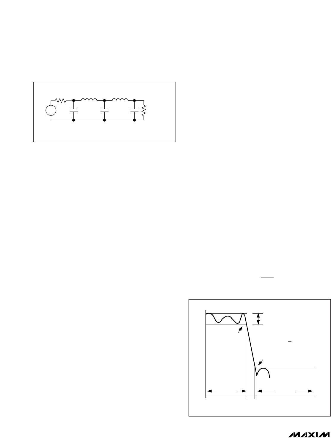
An SCF that emulates a passive ladder filter retains
many of the same advantages. The component sensi-
tivity of a passive ladder filter is low when compared to
a cascaded biquadratic design because each compo-
nent affects the entire filter shape rather than a single
pole-zero pair. In other words, a mismatched compo-
nent in a biquadratic design has a concentrated error
on its respective poles, while the same mismatch in a
ladder filter design spreads its error over all poles.
Elliptic Characteristics
Lowpass elliptic filters such as the MAX7418/MAX7421/
MAX7422/MAX7425 provide the steepest possible
rolloff with frequency of the four most common filter
types (Butterworth, Bessel, Chebyshev, and elliptic).
The high-Q value of the poles near the passband edge
combined with the stopband zeros allow for the sharp
attenuation characteristic of elliptic filters, making these
devices ideal for anti-aliasing and post-DAC filtering in
single-supply systems (see
Anti-Aliasing and Post-DAC
Filtering
).
In the frequency domain, the first transmission zero
causes the filter’s amplitude to drop to a minimum level
(Figure 2). Beyond this zero, the response rises as the
frequency increases until the next transmission zero.
The stopband begins at the stopband frequency, f
S
. At
frequencies above f
S
, the filter’s gain does not exceed
the gain at f
S
. The corner frequency, f
C
, is defined as
the point at which the filter output attenuation falls just
below the passband ripple. The transition ratio (r) is
defined as the ratio of the stopband frequency to the
corner frequency:
r = f
S
/ f
C
The MAX7418/MAX7422 have a transition ratio of 1.6
and typically 53dB of stopband rejection. The
MAX7421/MAX7425 have a transition ratio of 1.25 (pro-
viding a steeper rolloff) and typically 37dB of stopband
rejection.
Bessel Characteristics
Lowpass Bessel filters such as the MAX7419/MAX7423
delay all frequency components equally, preserving the
line up shape of step inputs (subject to the attenuation
of the higher frequencies). Bessel filters settle quickly—
an important characteristic in applications that use a
multiplexer (mux) to select an input signal for an ana-
log-to-digital converter (ADC). An anti-aliasing filter
placed between the mux and the ADC must settle
quickly after a new channel is selected.
Butterworth Characteristics
Lowpass Butterworth filters such as the MAX7420/
MAX7424 provide a maximally flat passband response,
making them ideal for instrumentation applications that
require minimum deviation from the DC gain throughout
the passband.
The difference between Bessel and Butterworth filters
can be observed when a 1kHz square wave is applied
to the filter input (Figure 3, trace A). With the filter cutoff
frequencies set at 5kHz, trace B shows the Bessel filter
response and trace C shows the Butterworth filter
response.
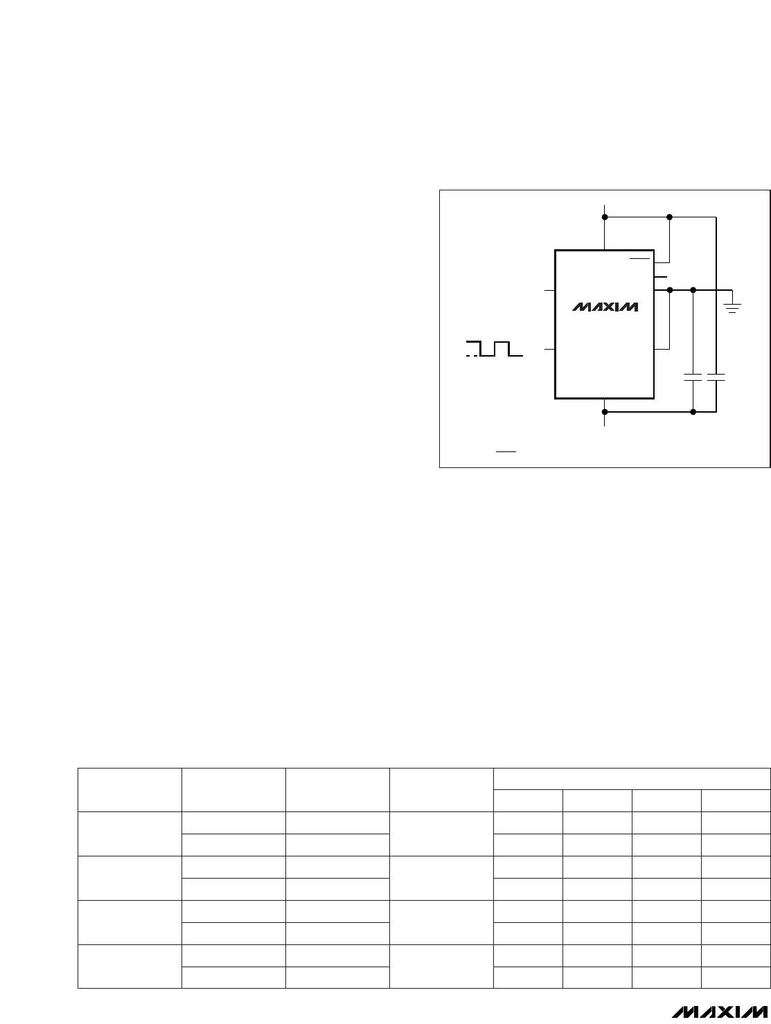
Clock Signal
External Clock
These SCFs are designed for use with external clocks
that have a 40% to 60% duty cycle. When using an
external clock, drive the CLK pin with a CMOS gate
powered from 0 to V
DD
. Varying the rate of the external
clock adjusts the corner frequency of the filter: