AZ23C15-7-F

AZ23C2V7 - AZ23C51
Document number: DS18003 Rev. 15 - 2
1 of 5
www.diodes.com
January 2013
© Diodes Incorporated
AZ23C2V7 -
A
Z23C51
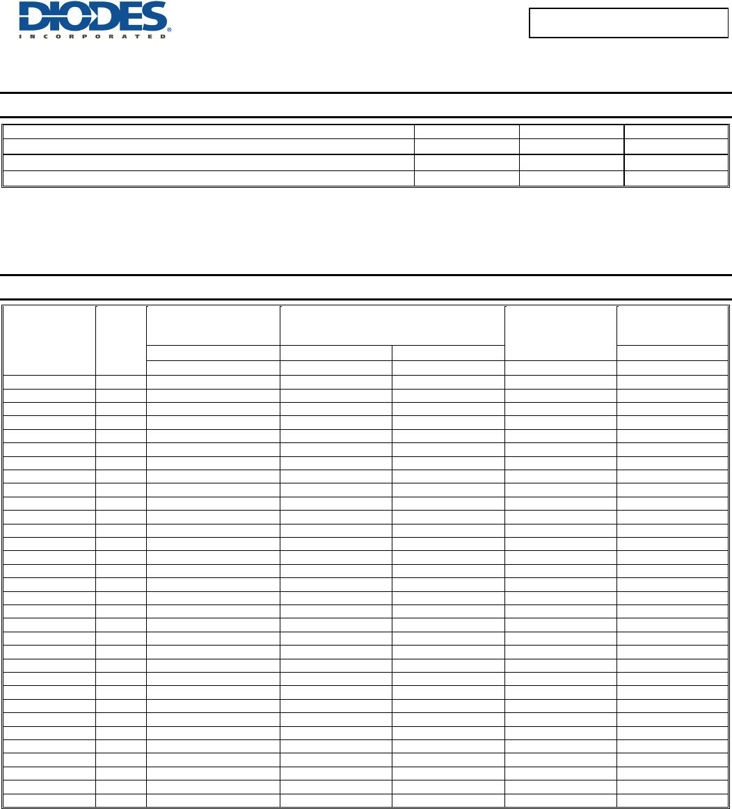
300mW DUAL SURFACE MOUNT ZENER DIODE
Features
Dual Zeners in Common Anode Configuration
300 mW Power Dissipation Rating
Ideally Suited for Automated Insertion
Δ V
Z
For Both Diodes in One Case is 5%
Common Cathode Style Available See DZ Series
Totally Lead-Free & Fully RoHS Compliant (Notes 1 & 2)
Halogen and Antimony Free. “Green” Device (Notes 3 & 4)
Qualified to AEC-Q101 Standards for High Reliability
ESD Sensitivity Rating
AEC-Q101, HBM - 8kV, MM - 400V
IEC 61000-4-2, Air - 15kV, Contact - 8kV
Mechanical Data
Case: SOT23
Case Material: Molded Plastic, “Green” Molding Compound.
UL Flammability Classification Rating 94V-0
Moisture Sensitivity: Level 1 per J-STD-020
Terminals: Matte Tin Finish annealed over Alloy 42 leadframe
(Lead Free Plating). Solderable per MIL-STD-202, Method 208
Polarity: See Diagram
Approximate Weight: 0.008 grams
Ordering Information (Note 5)
Part Number Qualification Case Packaging
(Type Number)-7-F* Commercial SOT23 3000/Tape & Reel
(Type Number)Q-7-F* Automotive SOT23 3000/Tape & Reel
*Add “-7-F” to the appropriate type number in Electrical Characteristics Table on Page 2 example: 6.2V Zener = AZ23C6V2-7F
Notes: 1. No purposely added lead. Fully EU Directive 2002/95/EC (RoHS) & 2011/65/EU (RoHS 2) compliant.
2. See http://www.diodes.com for more information about Diodes Incorporated’s definitions of Halogen- and Antimony-free, "Green" and Lead-free.
3. Halogen- and Antimony-free "Green” products are defined as those which contain <900ppm bromine, <900ppm chlorine (<1500ppm total Br + Cl) and
<1000ppm antimony compounds.
4. Product manufactured with Date Code V9 (week 33, 2008) and newer are built with Green Molding Compound. Product manufactured prior to Date
Code V9 are built with Non-Green Molding Compound and may contain Halogens or Sb
2
O
3
Fire Retardants.
5. For Packaging Details, go to our website at http://www.diodes.com.
Marking Information
Date Code Key
Year 1998 2002 2003 2004 2010 2011 2012 2013 2014 2015 2016 2017 2018
Code J N P R X Y Z A B C D E F
Month Jan Feb Mar Apr May Jun Jul Aug Sep Oct Nov Dec
Code 1 2 3 4 5 6 7 8 9 O N D
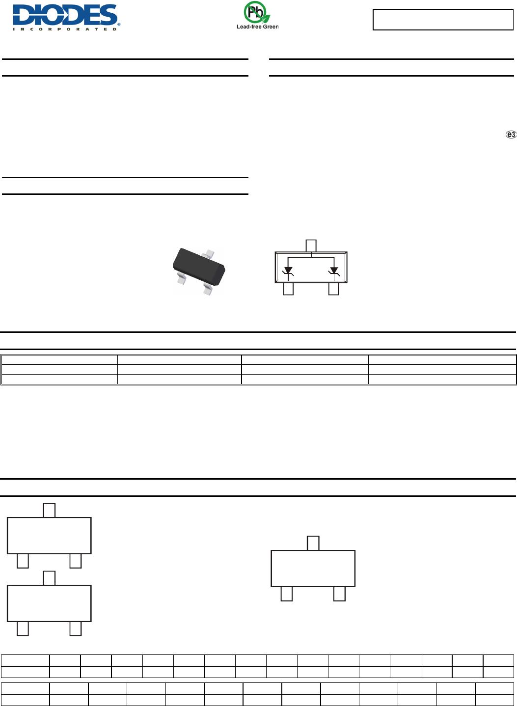
Device Schematic
K/D = SAT (Shanghai Assembly / Test site)
xx = Product Type Marking Code
See Electrical Characteristics Table
YM = Date Code Marking
Y = Year (ex: Z = 2012)
M
=
Month (ex: 9
=
September)
C = CAT (Chengdu Assembly / Test site)
xx = Product Type Marking Code
See Electrical Characteristics Table
YM = Date Code Marking
Y = Year (ex: Z = 2012)
M = Month (ex: 9 = September)
Cxx
YM
Kxx
YM
Dxx
YM
Top View
SOT23
AZ23C2V7 - AZ23C51
Document number: DS18003 Rev. 15 - 2
2 of 5
www.diodes.com
January 2013
© Diodes Incorporated
AZ23C2V7 -
A
Z23C51
Thermal Characteristics
Characteristic Symbol Value Unit
Power Dissipation (Note 6)
P
D
300 mW
Thermal Resistance, Junction to Ambient Air (Note 6)
R
θ
JA
417 °C/W
Operating and Storage Temperature Range
T
J
, T
STG
-65 to +150 °C
Notes: 6. Mounted on FR4 PC Board with recommended pad layout which can be found on our website at http://www.diodes.com.
Electrical Characteristics (@T
A
= +25°C, unless otherwise specified.)
Type
Number
Marking
Code
Zener
Voltage Range
(Note 7)
Maximum
Zener Impedance
f = 1kHz
Typical
Temperature
Coefficient
Min.
Reverse
Voltage (Note 7)
@ I
ZT
= 5.0mA Z
ZT
@ I
ZT
= 5.0mA Z
Z
K
@ I
Z
K
= 1.0mA @ I
R
= 0.1µA
V
Z
(Volts)
Ohms Ohms TC (%/°C)
V
R
(Volts)
AZ23C2V7 D1 2.5 - 2.9 83 500 -0.065
AZ23C3V0 D2 2.8 - 3.2 95 500 -0.060
AZ23C3V3 D3 3.1 - 3.5 95 500 -0.055
AZ23C3V6 D4 3.4 - 3.8 95 500 -0.055
AZ23C3V9 D5 3.7 - 4.1 95 500 -0.050
AZ23C4V3 D6 4.0 - 4.6 95 500 -0.035
AZ23C4V7 D7 4.4 - 5.0 78 500 -0.015
AZ23C5V1 D8 4.8 - 5.4 60 480 +0.005 0.8
AZ23C5V6 D9 5.2 - 6.0 40 400 +0.020 1.0
AZ23C6V2 DA 5.8 - 6.6 10 200 +0.030 2.0
AZ23C6V8 DB 6.4 - 7.2 8.0 150 +0.045 3.0
AZ23C7V5 DC 7.0 - 7.9 7.0 50 +0.050 5.0
AZ23C8V2 DD 7.7 - 8.7 7.0 50 +0.055 6.0
AZ23C9V1 DE 8.5 - 9.6 10 50 +0.065 7.0
AZ23C10 DF 9.4 - 10.6 15 70 +0.065 7.5
AZ23C11 DG 10.4 - 11.6 20 70 +0.070 8.5
AZ23C12 DH 11.4 - 12.7 20 90 +0.075 9.0
AZ23C13 DI 12.4 - 14.1 25 110 +0.080 10.0
AZ23C15 DJ 13.8 - 15.6 30 110 +0.080 11.0
AZ23C16 DK 15.3 - 17.1 40 170 +0.090 12.0
AZ23C18 DL 16.8 - 19.1 50 170 +0.090 14.0
AZ23C20 DM 18.8 - 21.2 50 220 +0.090 15.0
AZ23C22 DN 20.8 - 23.3 55 220 +0.090 17.0
AZ23C24 DO 22.8 - 25.6 80 220 +0.090 18.0
AZ23C27 DP 25.1 - 28.9 80 250 +0.090 20.0
AZ23C30 DQ 28 - 32 80 250 +0.090 22.5
AZ23C33 DR 31 - 35 80 250 +0.090 25.0
AZ23C36 DS 34 - 38 90 250 +0.090 27.0
AZ23C39 DT 37 - 41 90 300 +0.110 29.0
AZ23C43 30 40 - 46 100 700 +0.110 32.0
AZ23C47 31 44 - 50 100 750 +0.110 35.0
AZ23C51 32 48 - 54 100 750 +0.110 38.0
Notes: 7. Short duration pulse test used to minimize self-heating effect.
AZ23C2V7 - AZ23C51
Document number: DS18003 Rev. 15 - 2
3 of 5
www.diodes.com
January 2013
© Diodes Incorporated
AZ23C2V7 -
A
Z23C51
T , Ambient Temperature, (°C)
Fig. 1 Power Derating Curve
A
P
,
P
O
WE
R
DISSI
P
A
T
I
O
N (mW)
D
200
100
300
0
400
0
120 200
1608040
Note 6
0
10
20
30
40
50
0123456
7
8910
I, ZE
N
E
R
C
U
R
R
E
N
T
(mA)
Z
V , ZENER VOLTAGE (V)
Fig. 2 Typical Zener Breakdown Characteristics
Z
0
10
20
30
0
I, ZE
N
E
R
C
U
R
R
E
N
T
(mA)
Z
V , ZENER VOLTAGE (V)
Fig. 3 Typical Zener Breakdown Characteristics
Z
10 20 30 40
T = 25°C
J
Test Current I
5mA
Z
C10
C12
C18
C22
C27
C33
C36
C15
0
2
4
6
8
10
100 203040506070 8090100
I, ZENE
R
C
U
R
R
EN
T
(mA)
Z
V , ZENER VOLTAGE (V)
Fig. 4 Typical Zener Breakdown Characteristics
Z
C , TOTAL CAPACITANCE (pF)
T
10
100
1,000
10
1001
V , NOMINAL ZENER VOLTAGE (V)
Fig. 5 Typical Total Capacitance vs. Nominal Zener Voltage
Z
T= 25 °C
J
V = 1V
R
V = 2V
R
V = 1V
R
V = 2V
R

AZ23C15-7-F

Mfr. #:
Manufacturer:
Diodes Incorporated
Description:
Zener Diodes 300mW 15V Dual Zener AEC-Q101 Qualified
Lifecycle:
New from this manufacturer.
Delivery:
DHL FedEx Ups TNT EMS
Payment:
T/T Paypal Visa MoneyGram Western Union