VJ OMD Series
www.vishay.com
Vishay Vitramon
Revision: 25-Mar-13
13
Document Number: 45198
For technical questions, contact: mlcc@vishay.com
THIS DOCUMENT IS SUBJECT TO CHANGE WITHOUT NOTICE. THE PRODUCTS DESCRIBED HEREIN AND THIS DOCUMENT
ARE SUBJECT TO SPECIFIC DISCLAIMERS, SET FORTH AT www.vishay.com/doc?91000
X7R DIELECTRIC - TYPICAL PARAMETERS
DC VOLTS APPLIED
% CAPACITANCE CHANGE
10
0
- 10
- 20
- 30
- 40
- 50
- 60
- 70
- 80
- 90
VOLTAGE COEFFICIENT OF CAPACITANCE
HIGHER CAPACITANCE
0
100
200
300
400
500
600
700
Case Size
1206
1210
1812
Range
5600 pF to 18 000 pF
12 000 pF to 39 000 pF
33 000 pF to 100 000 pF
VOLTAGE COEFFICIENT OF CAPACITANCE
DC VOLTS APPLIED
% CAPACITANCE CHANGE
0 500 1000 1500 2000 2500
10
0
- 10
- 20
- 30
- 40
- 50
- 60
- 70
- 80
1000 V/1500 V RATED
2000 V RATED
VJ OMD Series
www.vishay.com
Vishay Vitramon
Revision: 25-Mar-13
14
Document Number: 45198
For technical questions, contact: mlcc@vishay.com
THIS DOCUMENT IS SUBJECT TO CHANGE WITHOUT NOTICE. THE PRODUCTS DESCRIBED HEREIN AND THIS DOCUMENT
ARE SUBJECT TO SPECIFIC DISCLAIMERS, SET FORTH AT www.vishay.com/doc?91000
BOARDFLEX SENSITIVE APPLICATIONS - SOLUTION:
A predominant failure mode in multilayer ceramic chip capacitors is cracking caused by board flexure. Cracks can then create
a path for current to pass from one electrode through the dielectric to an opposing electrode or from the terminations at one
end of the MLCC through the dielectric to an opposing electrode. This may subsequently result in capacitance loss, leakage -
low Insulation Resistance (IR) - and/or more seriously, high current shorts. A short circuit condition in the surface mounted
capacitors can cause further failures of downstream components. Vishay’s Open Mode Design Capacitors (VJ OMD - Cap.
series) reduce the risk of these destructive conditions through MLCC designs that prevent board flexure cracks reaching the
opposing electrode.
VJ OMD - Cap. MLCCs reduce the risk of early field failures associated with board flex cracks. However, it is important to note
that even in the open mode designs the presence of flexure related cracks can cause capacitance loss leading to localized
stresses on the parts. eventually, depending on the application environment, including such factors and high voltage pulse
frequency and thermal cycling this may lead to internal breakdown of the component.
POLYMER TERMINATION
Polymer termination provides additional protection against board flexure damage by absorbing greater mechanical and thermal
stresses. Components can be packaged, transported, stored and handled the same standard terminated product. Wave and
reflow soldering of MLCC does not require modification to equipment and/or process. Polymer termination greatly reduces the
risk of mechanical cracking however it does not completely eliminate.
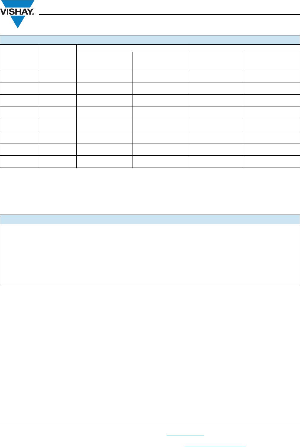
STANDARD TERMINATION OMD CAP PLUS POLYMER TERMINATION
Exposed Electrodes = Electrical short No Exposed Electrodes = No Electrical short
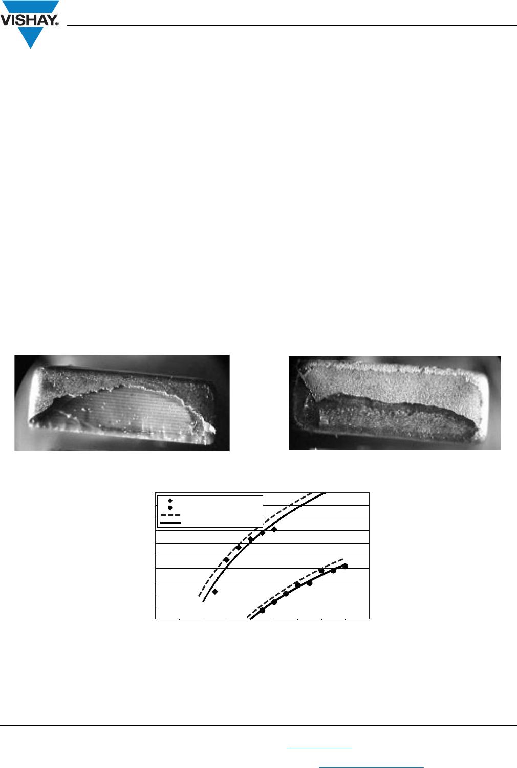
TYPICAL BEND TEST RESULTS 2220 CASE SIZE
0.0
1.0 2.0 3.0 4.0 5.0 6.0 7.0 8.0 9.0
Log. (Polymer Termination)
Polymer Termination
Log. (Standard Termination)
Standard Termination
BOARD FLEXURE in (mm)
FAILED PERCENTAGE OF PARTS
0 %
10 %
20 %
30 %
40 %
50 %
60 %
70 %
80 %
90 %
100 %
VJ OMD Series
www.vishay.com
Vishay Vitramon
Revision: 25-Mar-13
15
Document Number: 45198
For technical questions, contact: mlcc@vishay.com
THIS DOCUMENT IS SUBJECT TO CHANGE WITHOUT NOTICE. THE PRODUCTS DESCRIBED HEREIN AND THIS DOCUMENT
ARE SUBJECT TO SPECIFIC DISCLAIMERS, SET FORTH AT www.vishay.com/doc?91000
Notes
(1)
Vishay Vitramon uses embossed plastic, and punch paper carrier tapes. Paper tape is not available for case sizes > 1206 or for component
thickness > 0.035" (0.89 mm)
(2)
Reference: EIA standard RS 481 - “Taping of Surface Mount Components for Automatic Placement”
(3)
n/a = Not available
(4)
Packaging code “C/O”, “P/I” and lower quantities can depend from product thickness
STANDARD PACKAGING QUANTITIES
(1)(2)(3)
CASE CODE TAPE SIZE
7" REEL QUANTITIES 11 1/4" AND 13" REEL QUANTITIES
PAPER TAPE
PACKAGING CODE
“C”/”O
PLASTIC TAPE
PACKAGING CODE “T”
PAPER TAPE
PACKAGING CODE
“P”/”I”
PLASTIC TAPE
PACKAGING CODE
“R”
0805
(4)
8 mm 3000 3000 10 000 10 000
1206
(4)
8 mm n/a 3000/2500 n/a 10 000/9000
1210
(4)
8 mm n/a 3000/2500/2000 n/a 10 000/9000
1808
(4)
12 mm n/a 2000 n/a 10 000
1812
(4)
12 mm n/a 1000 n/a 4000
1825 12 mm n/a 1000 n/a 4000
2220 12 mm n/a 1000 n/a 4000
2225 12 mm n/a 1000 n/a 4000
STORAGE AND HANDLING CONDITIONS
(1) Store the components at 5 °C to + 40 °C ambient temperature and 70 % related humidity conditions.
(2) The product is recommended to be used within a time-frame of 2 years after shipment.
Check solderability in case extended shelf life beyond the expiry date is needed.
Precautions:
a. Do not store products in an environment containing corrosive elements, especially where chloride gas, sulfide gas, acid, alkali, salt or
the like are present. This may cause corrosion or oxidization of the terminations, which can easily lead to poor soldering.
b. Store products on the shelf and avoid exposure to moisture or dust.
c. Do not expose products to excessive shock, vibration, direct sunlight and so on.

VJ1206Y103KBBAT4X

Mfr. #:
Manufacturer:
Vishay
Description:
Multilayer Ceramic Capacitors MLCC - SMD/SMT 10nF 100volts 10%
Lifecycle:
New from this manufacturer.
Delivery:
DHL FedEx Ups TNT EMS
Payment:
T/T Paypal Visa MoneyGram Western Union