VJ OMD Series
www.vishay.com
Vishay Vitramon
Revision: 25-Mar-13
1
Document Number: 45198
For technical questions, contact: mlcc@vishay.com
THIS DOCUMENT IS SUBJECT TO CHANGE WITHOUT NOTICE. THE PRODUCTS DESCRIBED HEREIN AND THIS DOCUMENT
ARE SUBJECT TO SPECIFIC DISCLAIMERS, SET FORTH AT www.vishay.com/doc?91000
Surface Mount Multilayer Ceramic Chip Capacitor Solutions for
Boardflex Sensitive Applications
FEATURES
Open Mode Design (OMD) reduces risk of
shorts or leakage in board flex applications
Excellent reliability and thermal shock
performance
Efficient low-power consumption, ripple
current capable to 1.2 A
RMS
at 100 kHz
High voltage breakdown compared to
standard design
100 % voltage conditioning available up to
630 V
DC
rating (process code “5H”)
Contact mlcc@vishay.com
for higher voltages.
Polymer termination available for intensive board flex
requirements
Wet build process
Reliable Noble Metal Electrode (NME) system
Material categorization: For definitions of compliance
please see www.vishay.com/doc?99912
APPLICATIONS
Demanding boardflex applications
Input filter capacitors
Output filter capacitors
Snubber capacitors reduce MOSFET voltage spikes
High frequency filtering for switching power supplies
For lighting and other AC applications please contact:
mlcc@vishay.com
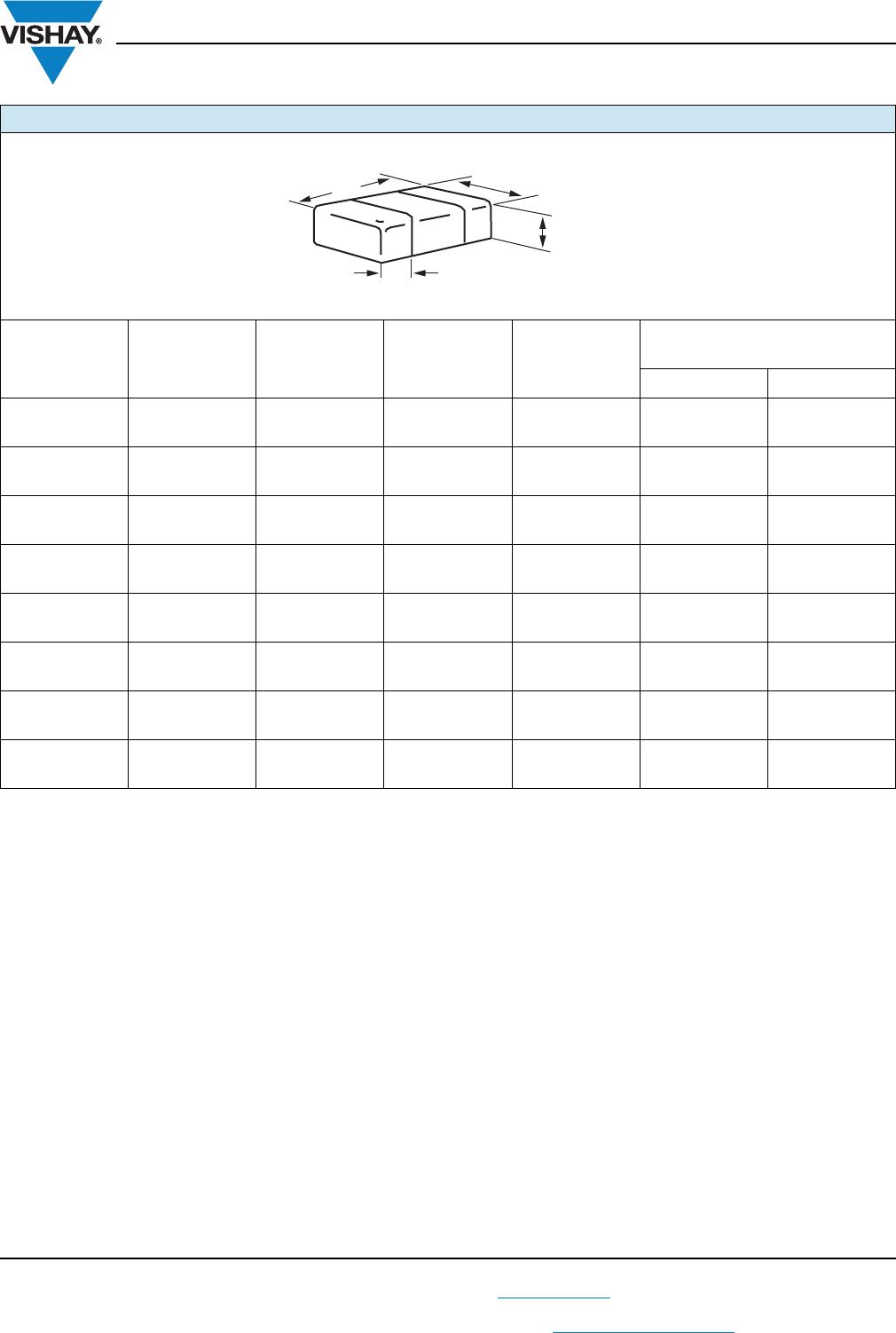
ELECTRICAL SPECIFICATIONS
C0G (NP0)
GENERAL SPECIFICATION
Note
Electrical characteristics at + 25 °C unless otherwise specified
Operating Temperature: - 55 °C to + 125 °C
Capacitance Range: 10 pF to 47 nF
Voltage Range
: 50 V
DC
to 3000 V
DC
Temperature Coefficient of Capacitance (TCC):
0 ppm/°C ± 30 ppm/°C from - 55 °C to + 125 °C
Dissipation Factor (DF):
0.1 % maximum at 1.0 V
RMS
and
1 MHz for values 1000 pF
0.1 % maximum at 1.0 V
RMS
and
1 kHz for values > 1000 pF
Insulating Resistance:
At + 25 °C 100 000 M min. or 1000 F whichever is less
At + 125 °C 10 000 M min. or 100 F whichever is less
Aging Rate
: 0 % maximum per decade
Dielectric Strength Test:
Performed per method 103 of EIA 198-2-E
Applied test voltages
200 V
DC
-rated: 250 % of rated voltage
500 V
DC
-rated: 200 % of rated voltage
630 V
DC
/1000 V
DC
-rated: 150 % of rated voltage
1500 V
DC
to 3000 V
DC
-rated: 120 % of rated voltage
X7R
GENERAL SPECIFICATION
Note
Electrical characteristics at + 25 °C unless otherwise specified
Operating Temperature: - 55 °C to + 125 °C
Capacitance Range
: 100 pF to 1.8 μF
Voltage Range
: 16 V
DC
to 3000 V
DC
Temperature Coefficient of Capacitance (TCC):
± 15 % from - 55 °C to + 125 °C, with 0 V
DC
applied
Dissipation Factor (DF):
< 50 V ratings 3.5 % maximum at 1.0 V
RMS
and 1 kHz
50 V ratings 2.5 % maximum at 1.0 V
RMS
and 1 kHz
Insulating Resistance:
At + 25 °C 100 000 M min. or 1000 F whichever is less
At + 125 °C 10 000 M min. or 100 F whichever is less
Aging Rate: 1 % maximum per decade
Dielectric Strength Test:
Performed per method 103 of EIA 198-2-E
Applied test voltages
250 V
DC
-rated: 250 % of rated voltage
500 V
DC
-rated: min. 150 % of rated voltage
630 V
DC
/1000 V
DC
-rated: 150 % of rated voltage
1500 V
DC
to 3000 V
DC
-rated: 120 % of rated voltage
VJ OMD Series
www.vishay.com
Vishay Vitramon
Revision: 25-Mar-13
2
Document Number: 45198
For technical questions, contact: mlcc@vishay.com
THIS DOCUMENT IS SUBJECT TO CHANGE WITHOUT NOTICE. THE PRODUCTS DESCRIBED HEREIN AND THIS DOCUMENT
ARE SUBJECT TO SPECIFIC DISCLAIMERS, SET FORTH AT www.vishay.com/doc?91000
Note
Detail ratings see “Selection Chart”
Notes
(1)
DC voltage rating should not be exceeded in application. Other application factors may affect the MLCC performance.
Consult for questions: mlcc@vishay.com
(2)
Process code with 2 digits has to be added.
(3)
Termination code E” is for conductive epoxy assembly.
QUICK REFERENCE DATA
DIELECTRIC CASE
MAXIMUM VOLTAGE
(V)
CAPACITANCE
MINIMUM MAXIMUM
C0G (NP0)
1206 1500 10 pF 4.7 nF
1210 2000 10 pF 8.2 nF
1808 3000 10 pF 8.2 nF
1812 3000 10 pF 18 nF
1825 1000 15 pF 33 nF
2220 1000 270 pF 39 nF
2225 1000 270 pF 47 nF
X7R
0805 630 470 pF 220 nF
1206 2000 270 pF 680 nF
1210 2000 390 pF 1.0 μF
1808 3000 220 pF 18 nF
1812 3000 100 pF 1.2 μF
1825 2000 5.6 nF 1.5 μF
2220 3000 1.0 nF 1.8 μF
2225 2000 5.6 nF 1.8 μF
ORDERING INFORMATION
VJ1210 Y 474 J X A A T #
(2)
CASE
CODE
DIELECTRIC CAPACITANCE
NOMINAL
CODE
CAPACITANCE
TOLERANCE
TERMINATION DC
VOLTAGE
RATING
(1)
MARKING PACKAGING PROCESS
CODE
0805
1206
1210
1808
1812
1825
2220
2225
A = C0G
(NP0)
Y = X7R
Expressed in
picofarads (pF).
The first two
digits are
significant, the
third is a
multiplier. An “R”
indicates a
decimal point.
Examples
474 = 470 000 pF
F = ± 1 %
G = ± 2 %
J = ± 5 %
K = ± 10 %
M = ± 20 %
Note
C0G (NP0):
F, G, J, K
X7R:
J, K, M
X = Ni barrier
100 % tin plated
matte finish
F, E = AgPd
(3)
B = Polymer
100 % tin plated
matte finish
N =
Non-magnetic
J = 16 V
X = 25 V
A = 50 V
B = 100 V
C = 200 V
P = 250 V
E = 500 V
L = 630 V
G = 1000 V
R = 1500 V
F = 2000 V
H = 3000 V
A =
Unmarked
4X =
OMD cap
5H =
OMD cap
100 %
voltage
conditioning
C = 7" reel/paper tape
T = 7" reel/plastic tape
P = 11 1/4"/13" reel/
paper tape
R = 11 1/4"/13" reel/
plastic tape
O = 7" reel/flamed
paper tape
Note
“I” and “O” are used for
“F”, “E” termination
size 0805
ENVIRONMENTAL STATUS
TERMINATION CODE TERMINATION DESCRIPTION RoHS COMPLIANT VISHAY GREEN
X Ni barrier 100 % tin plated matte finish Yes Yes
EAgPdYesYes
B Polymer layer, 100 % tin plated matte finish Yes No
FAgPdYesNo
NNon-magneticYesNo
VJ OMD Series
www.vishay.com
Vishay Vitramon
Revision: 25-Mar-13
3
Document Number: 45198
For technical questions, contact: mlcc@vishay.com
THIS DOCUMENT IS SUBJECT TO CHANGE WITHOUT NOTICE. THE PRODUCTS DESCRIBED HEREIN AND THIS DOCUMENT
ARE SUBJECT TO SPECIFIC DISCLAIMERS, SET FORTH AT www.vishay.com/doc?91000
Note
Polymer (B-termination) have increased dimensions:
Length 0.006" (0.15 mm)
DIMENSIONS in inches (millimeters)
CASE CODE STYLE
LENGTH
(L)
WIDTH
(W)
MAXIMUM
THICKNESS
(T)
TERMINATION PAD
(P)
MINIMUM MAXIMUM
0805 VJ0805
0.079 ± 0.008
(2.00 ± 0.20)
0.049 ± 0.008
(1.25 ± 0.20)
0.057 (1.45) 0.010 (0.25) 0.028 (0.71)
1206 VJ1206
0.126 ± 0.008
(3.20 ± 0.20)
0.063 ± 0.008
(1.60 ± 0.20)
0.067 (1.70) 0.010 (0.25) 0.028 (0.71)
1210 VJ1210
0.126 ± 0.008
(3.20 ± 0.20)
0.098 ± 0.008
(2.50 ± 0.20)
0.067 (1.70) 0.010 (0.25) 0.028 (0.71)
1808 VJ1808
0.180 ± 0.012
(4.57 ± 0.30)
0.080 ± 0.010
(2.03 ± 0.25)
0.086 (2.18) 0.010 (0.25) 0.030 (0.76)
1812 VJ1812
0.177 ± 0.012
(4.50 ± 0.30)
0.126 ± 0.008
(3.20 ± 0.20)
0.086 (2.18) 0.010 (0.25) 0.030 (0.76)
1825 VJ1825
0.177 ± 0.012
(4.50 ± 0.30)
0.252 ± 0.010
(6.40 ± 0.25)
0.086 (2.18) 0.010 (0.25) 0.030 (0.76)
2220 VJ2220
0.220 ± 0.010
(5.59 ± 0.25)
0.200 ± 0.010
(5.08 ± 0.25)
0.086 (2.18) 0.010 (0.25) 0.030 (0.76)
2225 VJ2225
0.220 ± 0.010
(5.59 ± 0.25)
0.250 ± 0.010
(6.35 ± 0.25)
0.086 (2.18) 0.010 (0.25) 0.030 (0.76)
L
W
T
MAX.
P

VJ1825Y224KBEAT4X

Mfr. #:
Manufacturer:
Vishay
Description:
Multilayer Ceramic Capacitors MLCC - SMD/SMT .22uF 500volts 10%
Lifecycle:
New from this manufacturer.
Delivery:
DHL FedEx Ups TNT EMS
Payment:
T/T Paypal Visa MoneyGram Western Union