USBDFxxW5 Application information
7/11
Figure 8. gives the measurement circuit for the analog crosstalk application. In Figure 10.,
the curve shows the effect of the D+ cell on the D- cell. In usual frequency range of analog
signals (up to 100 MHz) the effect on disturbed line is less than -46 dB.
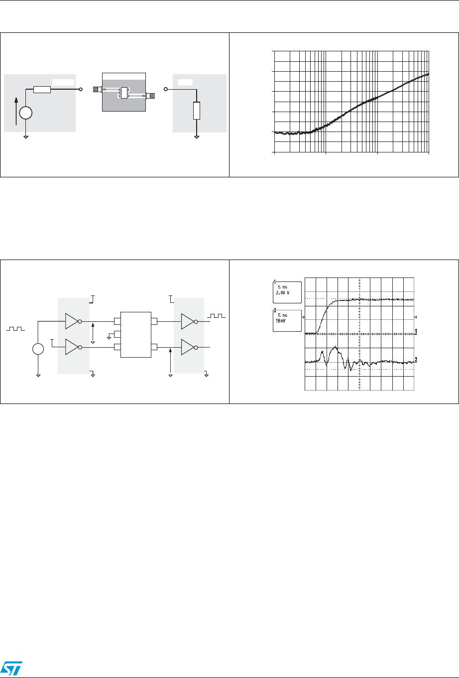
Figure 11. shows the measurement circuit used to quantify the crosstalk effect in a classical
digital application.
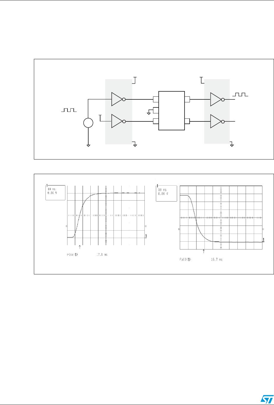
Figure 12. shows that in such a condition signal, from 0 to 5 V and rise time of few ns, the
impact on the other line is less than 100 mV peak to peak (below the logic high voltage
threshold). The measurements performed with falling edges give the same results.
Figure 9. Analog crosstalk measurements Figure 10. Typical analog crosstalk results
50 Ω
RF IN
Vg
50 Ω
TG OUT
TEST BOARD
UD1
1 10 100 1,000
-100
-80
-60
-40
-20
0
frequency (MHz)
Analog crosstalk (dB)
Figure 11. Digital crosstalk measurements
configuration
Figure 12. Digital crosstalk results
Line 1
Line 2
V
G1
b
21
V
G1
+5V +5V
74HC04
+5V
Square
Pulse
Generator
5KHz
74HC04
USBDF
xxW5